Yaw control device for a nozzle having a rectangular outlet section

a control device and nozzle technology, applied in the field of aircraft, can solve the problem that the control surface deflecting only temporarily generates thrust loss, and achieve the effect of limiting thrust loss and impact loss and good yaw momen

Inactive Publication Date: 2009-12-08
SNECMA PROPULSION SOLIDE
View PDF16 Cites 6 Cited by
  • Summary
  • Abstract
  • Description
  • Claims
  • Application Information

AI Technical Summary

Benefits of technology

[0006]The present invention seeks to provide a solution to the problem posed by achieving yaw control in aircraft without a vertical fin and fitted with a supersonic nozzle of rectangular or flat section, which solution enables a good yaw moment to be generated about the center of gravity of the aircraft, while limiting losses of thrust and impact on the thermodynamic cycle of the engine.
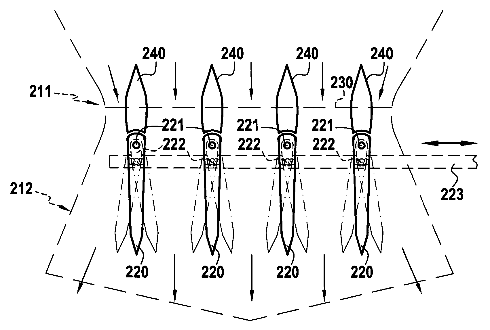
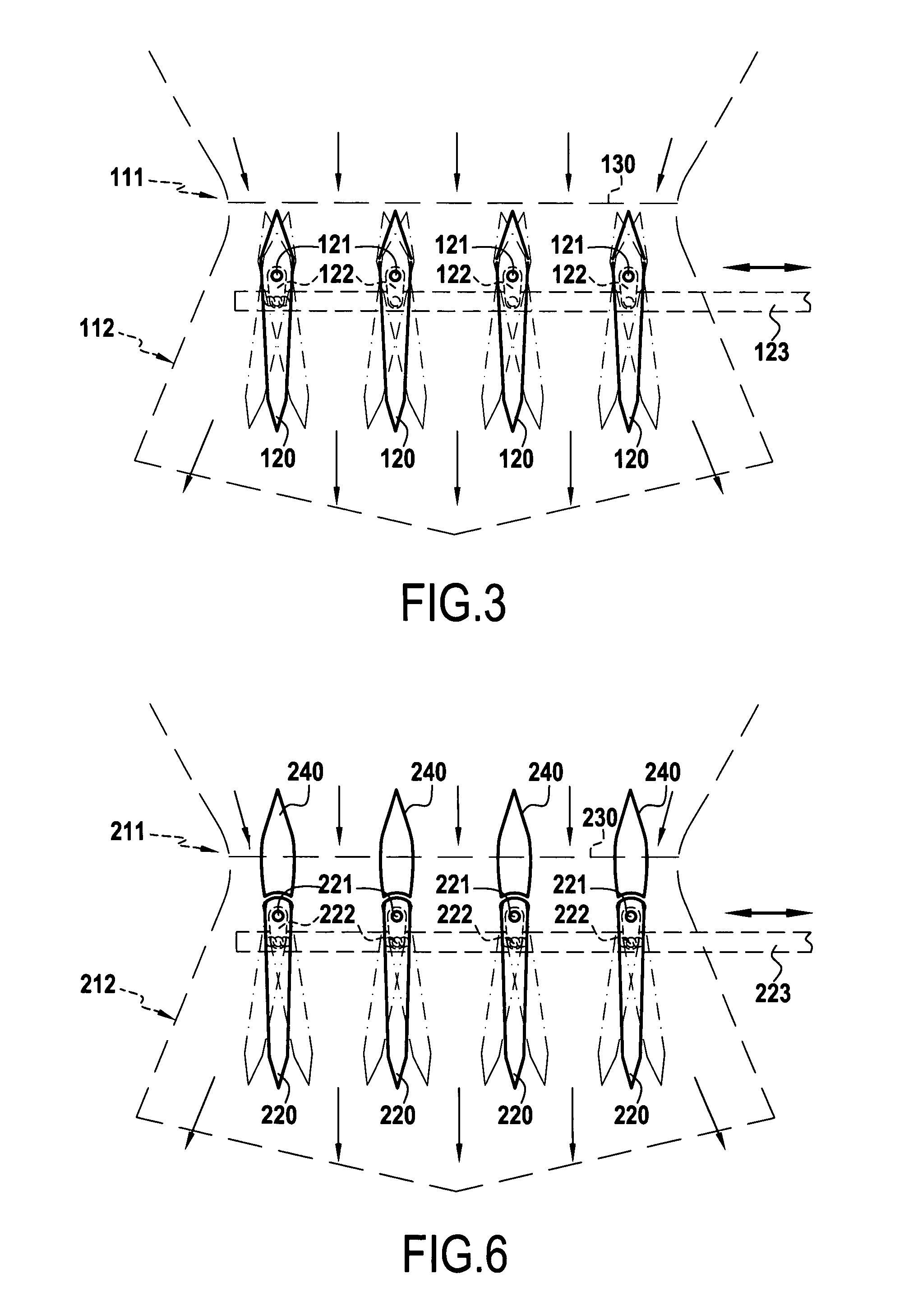
[0007]In accordance with the present invention, this object is achieved by a yaw control device comprising at least one jet control surface in the form of an airfoil placed in the diverging portion of the nozzle, said control surface being movable about a pivot axis in order to generate a lateral force when in a deflected position, so as to enable the aircraft to turn about its yaw axis. The yaw control device further comprises a stationary element disposed upstream from the or each jet control surface in the nozzle, said stationary element presenting an aerodynamic leading edge in order to protect the control surface from the supersonic flow in the nozzle.
[0011]Placing a stationary element upstream from each control surface serves to protect them from the supersonic flow while they are in the non-deflected position, and thus serves to reduce loss of thrust in continuous operation. The presence of one or more jet control surfaces in the supersonic flow generates shockwaves therein that induce losses of thrust. The stationary elements serve to “mask” the supersonic flow control surfaces when they are in the non-deflected position. For this purposes, the stationary elements are preferably located at least in part upstream of the sonic cutoff line in the nozzle. With these stationary elements, the device of the invention has negligible impact on the thrust performance of the engine so long as the device is not activated (i.e. when the control surfaces are not deflected).
[0014]The invention also provides an aircraft including such a nozzle for which aircraft it is advantageously possible to eliminate the vertical fin, since the yaw control device is integrated in the nozzle.
[0015]Finally, the present invention provides a method of providing yaw control for an aircraft fitted with a supersonic nozzle of rectangular or flat section having a sonic throat extended by a diverging portion in which supersonic flow occurs, said method comprising placing at least one jet control surface in the form of an airfoil inside the diverging portion of the nozzle, placing a stationary element upstream from the or each jet control surface, the stationary element presenting an aerodynamic leading edge and serving to protect the control surface from the supersonic jet in the nozzle, the stationary element(s) preferably being located at least in part upstream of the sonic cutoff line of the nozzle, with deflection of the jet control surface serving to generate a lateral force that enables the aircraft to turn about its yaw axis.

Problems solved by technology

Deflecting the control surfaces generates thrust loss only temporarily.

Method used


Image

  • Yaw control device for a nozzle having a rectangular outlet section
  • Yaw control device for a nozzle having a rectangular outlet section
  • Yaw control device for a nozzle having a rectangular outlet section

Examples


Embodiment Construction

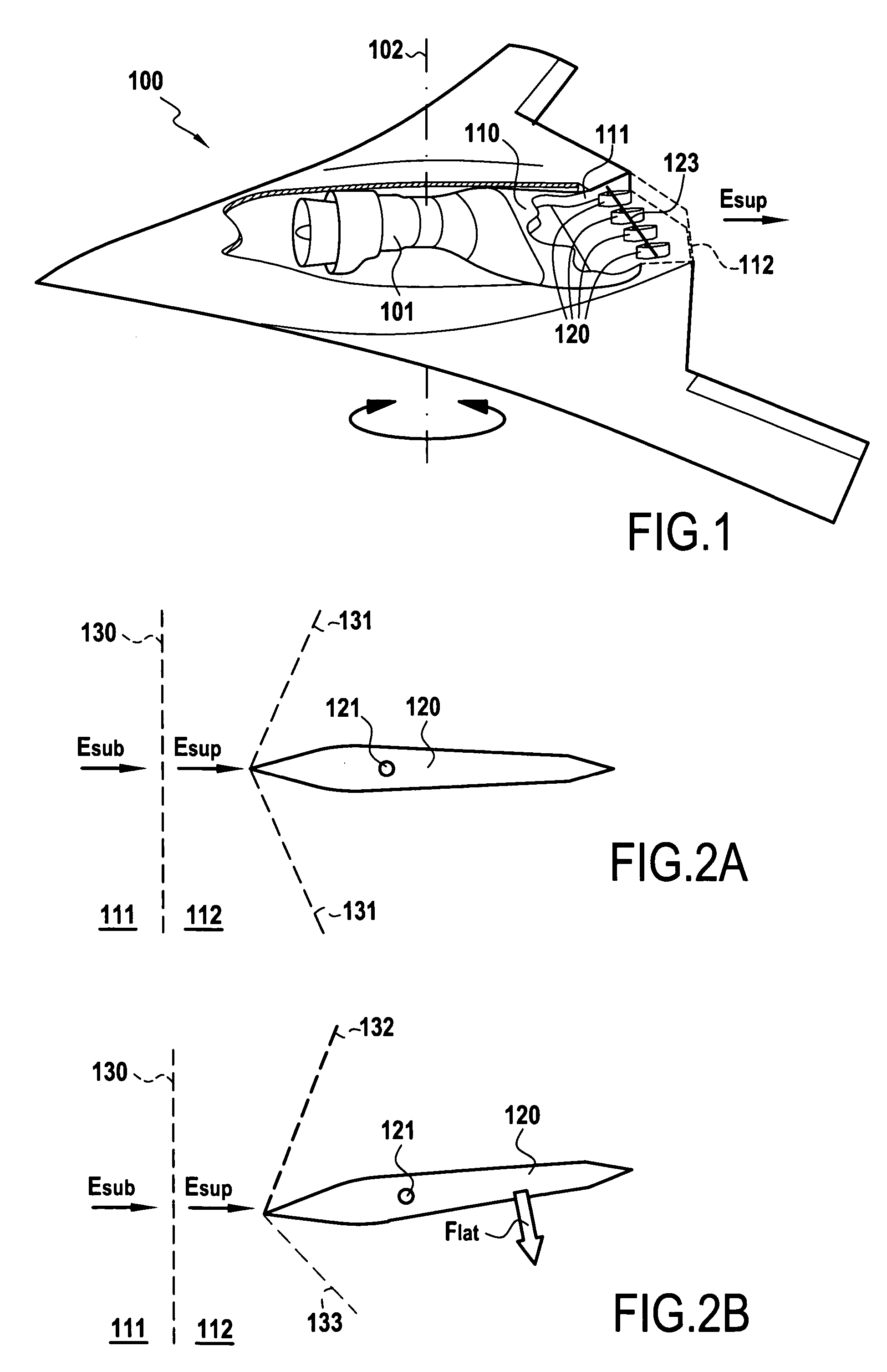
[0025]FIG. 1 is a highly diagrammatic view of an aircraft 100 of the unmanned combat air vehicle (UCAV) type, also known as a “drone”, which is fitted with an engine 101 whose rear portion is in the form of a supersonic nozzle 110 having a sonic throat 111 and a diverging portion 112. The nozzle 110 presents a plane or “two-dimensional” shape, i.e. its diverging portion 112 presents a flat or rectangular section, and at its outlet section its aspect ratio of width over height can be of the order of 3 or greater.

[0026]In order to conserve an airframe that is very flat in shape, the aircraft 100 does not have a vertical fin. In accordance with the invention, yaw control of the aircraft 100 is achieved by jet control surfaces 120 placed directly in the nozzle 110 so as to be subjected to the supersonic flow Esup of the jet which occurs in the diverging portion 112. As shown in FIG. 2A, each control surface 120 is in the form of an airfoil defining an aerodynamic profile for minimizing ...


PUM


Abstract

The invention relates to a yaw control device for an aircraft fitted with a supersonic nozzle having a rectangular or flat section comprising a supersonic throat extended by a diverging portion in which supersonic flow occurs. In order to enable the aircraft to be controlled in yaw in the absence of a vertical fin, the device of the invention makes use of jet control surfaces in the form of airfoils disposed in the diverging portion of the nozzle. The control surfaces are movable about respective pivot axes in order to generate a lateral force when in a deflected position, so as to enable the aircraft to turn about its yaw axis.

Description

[0001]This application claims priority to French application No. 05 07190 filed Jul. 7, 2005.BACKGROUND OF THE INVENTION[0002]The present invention relates to aircraft of the furtive type, i.e. to aircraft that are designed specifically to minimize their equivalent radar signature (ERS) and their infrared signature. By way of non-exclusive example, aircraft of this type are unmanned combat air vehicles (UCAVs), also known as “drones”, and because of the need for discretion (mainly in terms of ERS) they have airframes of a shape that is very flat without any vertical fin. In addition, the shape of the aircraft and the need for infrared discretion where the jet leaves the nozzle have led to the nozzle being given a so-called “two-dimensional” (or “2D”) shape with the outlet section of the nozzle being rectangular or flat in shape with an aspect ratio of width over height of the order of 3 or more.[0003]Eliminating the vertical fin (rudder) means that the aircraft must be given some ot...

Claims


Application Information

Patent Timeline
Patent Type & Authority Patents(United States)
IPC IPC(8): B64C9/38F02K1/12
CPCB64C15/02B64D33/04F02K1/002Y02T50/672F05D2250/324F05D2250/52F05D2220/80F05D2240/12F05D2250/12Y02T50/60
Inventor BUFFENOIR, FRANCOISLAFOND, ANDRE
Owner SNECMA PROPULSION SOLIDE
Why Eureka
Try Eureka