System for assisting regeneration of pollution management means

a pollution management and pollution management technology, applied in the direction of electrical control, exhaust treatment electric control, separation process, etc., can solve the problems of high fuel consumption, incompleteness, long service life,

Inactive Publication Date: 2009-12-15
PEZHO SITROEN AUTOMOBILS SA
View PDF15 Cites 18 Cited by
  • Summary
  • Abstract
  • Description
  • Claims
  • Application Information

AI Technical Summary

Benefits of technology

[0012]To this effect, an object of the invention is a system for assisting the regeneration of depollution means integrated in an exhaust line of a motor vehicle diesel engine, in which the engine is associated with common rail supply means for the injection of fuel into the cylinders thereof, according to at least one post-injection, and adapted to implement, at isotorque, through modification of parameters for controlling the operation of the engine, at least two regeneration strategies, among which a first regeneration strategy comprising strategies called level 1 strategies and level 2 strategies, and a second regeneration strategy comprising level 1 strategies and a sequence alternating level 2 strategies and over-calibrated level 2 strategies, making it possible to obtain different thermal levels in the exhaust line, characterized in that it comprises means for analyzing the driving conditions of the vehicle and means for comparison thereof with predetermined threshold values, to implement the first regeneration strategy for driving conditions above the threshold values or the second strategy for driving conditions below the threshold values.

Problems solved by technology

However, in critical driving conditions, such as, for example, city driving or in traffic jams, the levels reached with standard regeneration strategies of the particle filter can become insufficient to ensure a correct regeneration of the filter, which can translate into regenerations that last very long and are thus highly fuel-consuming, or even incomplete.

Method used


Image

  • System for assisting regeneration of pollution management means
  • System for assisting regeneration of pollution management means
  • System for assisting regeneration of pollution management means

Examples


Embodiment Construction

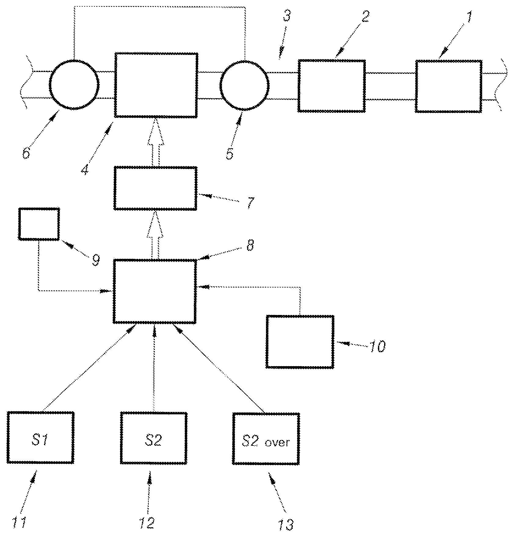
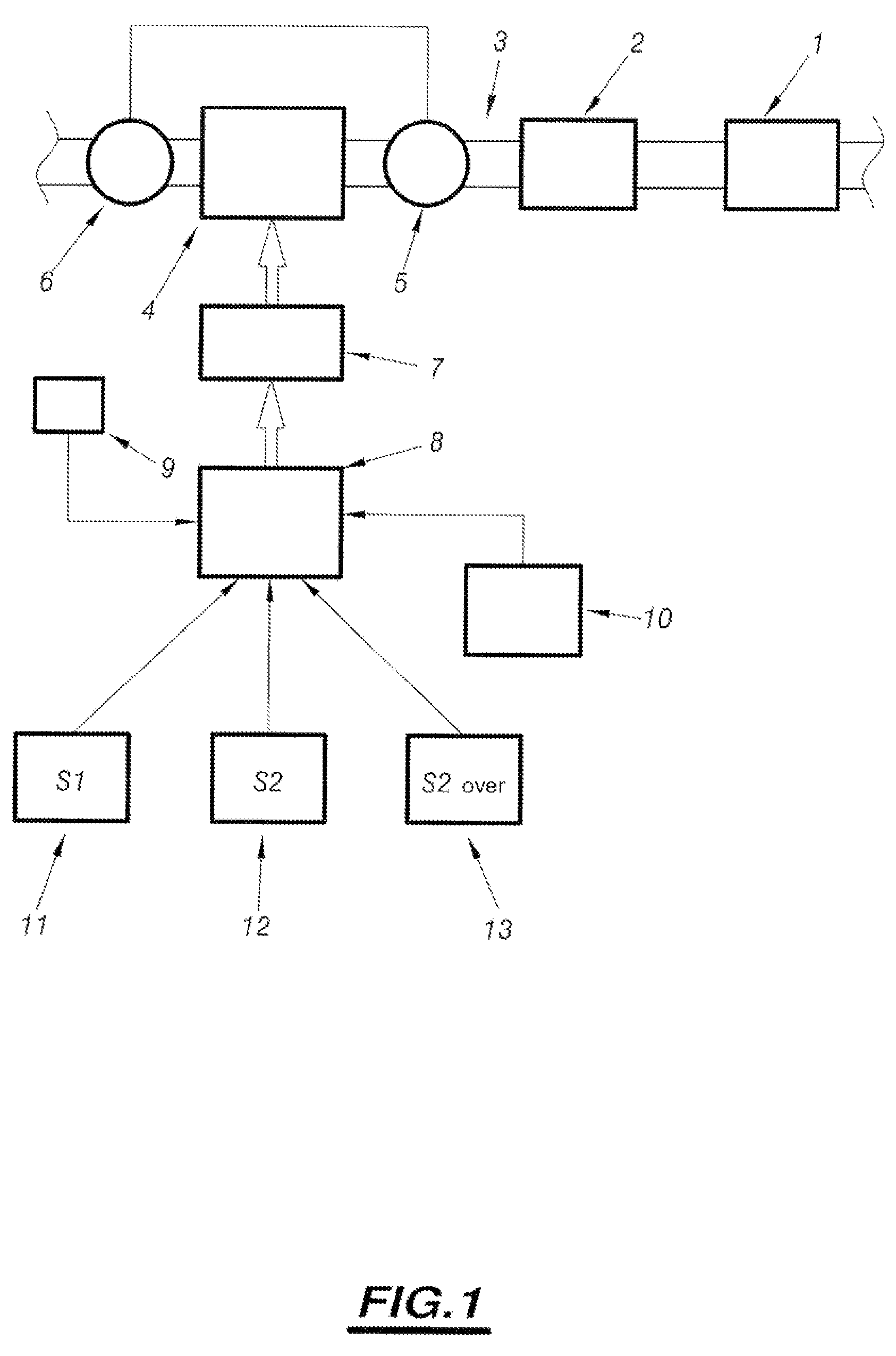
[0029]Indeed, FIG. 1 shows a system for assisting the regeneration of depollution means designated by the general reference 1, associated with means forming oxidation catalyst, designated by the general reference 2 and placed in an exhaust line 3 of a thermal engine such as a motor vehicle diesel engine.

[0030]This engine is designated by the general reference 4 and can be associated, for example, with a turbo-compressor whose turbine portion 5 is associated with the exhaust line and whose compressor portion 6 is placed upstream of the engine.

[0031]The engine is associated with common rail means for the supply of fuel to the cylinders thereof, designated by the general reference 7, whose operation is controlled by a supervisor 8.

[0032]According to the invention, this system also comprises means for analyzing the driving conditions of the vehicle and means for comparing these driving conditions with predetermined threshold values, to control the operation of the engine.

[0033]The analy...


PUM


Abstract

The invention concerns a system for assisting regeneration of pollution management means (1) integrated in an exhaust line (3) of a diesel engine (4), wherein the engine (4) is associated with common ramp means (7) injecting fuel into the cylinders thereof, based on at least one post-injection and adapted to implement, in isocouple, through modification of the engine operation control parameters, at least two strategies called level 1 and level 2 and a second regeneration strategy including level 1 strategies and a sequence alternating level 2 and over-calibrated level 2 strategies, enabling different thermal levels to be achieved in the exhaust line. The invention is characterized in that it comprises means (8) for analyzing the vehicle running conditions and means (8) for comparing same to threshold values, to implement the first regeneration strategy for running conditions higher than the threshold values or the second regeneration strategy for running conditions lower than the threshold values.

Description

BACKGROUND ART[0001]The present invention concerns a system for assisting the regeneration of depollution means integrated in an exhaust line of a motor vehicle diesel engine.[0002]More particularly, the invention concerns such a system in which the engine is associated to common rail means for the supply of fuel to its cylinders, according to at least one post-injection.[0003]Such a post-injection is, in a standard manner, an injection of fuel after the high dead center of the cylinder under consideration.[0004]These supply means are adapted to implement, in isocouple, through modification of parameters for controlling the operation of the engine, different regeneration strategies that make it possible to obtain different thermal states in the exhaust line.[0005]Thus, for example, supply means implementing a first regeneration strategy according to a strategy called level 1 strategy and a second regeneration strategy according to a strategy called level 2 strategy and / or an over-ca...

Claims


Application Information

Patent Timeline
Patent Type & Authority Patents(United States)
IPC IPC(8): F01N3/025B01D53/94F01N3/023F01N3/029F01N3/035F01N3/08F01N3/20F01N11/00F01N13/02F02B37/00F02D41/02F02D41/30F02D41/40
CPCB01D53/9495F01N3/0231F01N3/035F01N3/0842F01N13/009F02D41/029F02D41/405F01N2430/085F01N2550/04F02B37/00Y02T10/44F01N2510/065Y02A50/20Y02T10/40
Inventor COLIGNON, CHRISTOPHE
Owner PEZHO SITROEN AUTOMOBILS SA
Why Eureka
Try Eureka