
Receptacle connector

Active Publication Date: 2009-12-15
ADVANCED CONNECTEK INC
View PDF5 Cites 34 Cited by
  • Summary
  • Abstract
  • Description
  • Claims
  • Application Information

AI Technical Summary

Benefits of technology

[0004]The main objective of the present invention is to provide a receptacle connector with a high frequency transmission rate, which reduces electromagnetic interference (EMI), lowers production cost and improves structural strength.

Problems solved by technology

The transmission quality of the Display Port may be unstable at high frequency.
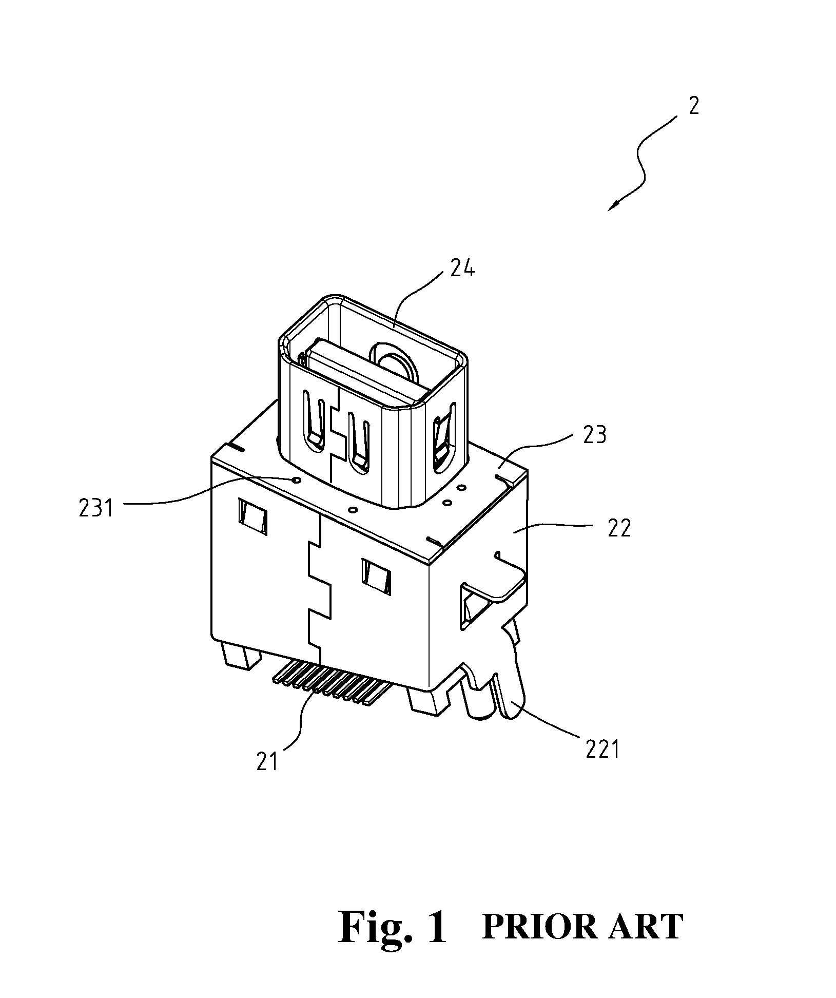
The three casings (22, 23, 24) may not connect perfectly to each other or an external force may reduce the transmission efficiency at high frequency.

Method used


Image

  • Receptacle connector
  • Receptacle connector
  • Receptacle connector

Examples


Embodiment Construction

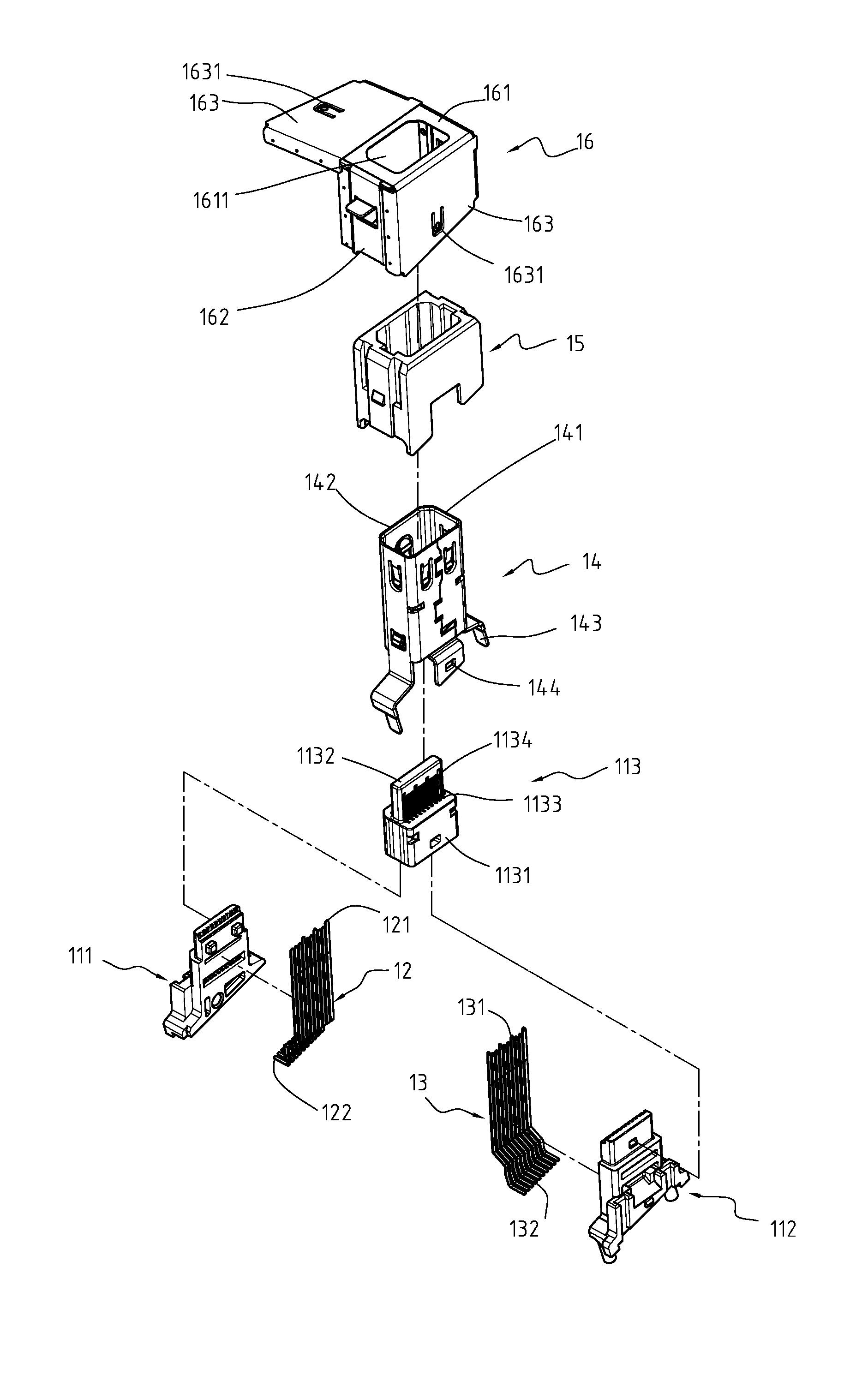
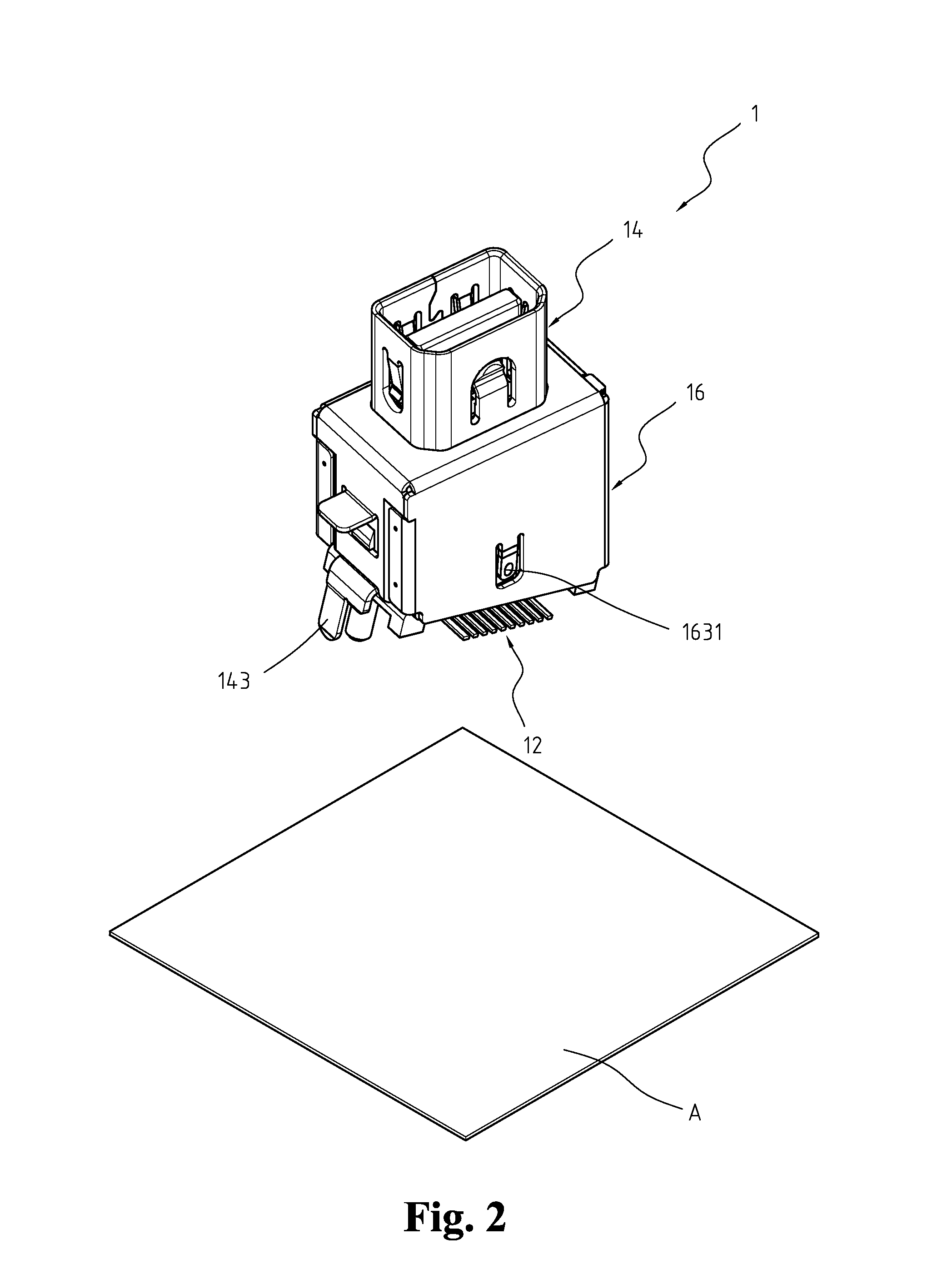
[0011]With reference to FIGS. 2 to 5, a receptacle connector (1) is a digital audio / video interface, is mounted on a printed circuit board (PCB) (A), protrudes through an electronic device casing and comprises an inner housing (11), 10 first pins (12), 10 second pins (13), an inner casing (14), an outer housing (15) and an outer casing (16).

[0012]The inner housing (11) is insulation, has an inner end and an outer end and comprises an inner first pin holder (111), an inner second pin holder (112) and an outer pin holder (113).

[0013]The inner first pin holder (111) has an inner end, an outer end, a base, a tongue and multiple pin passages. The base is formed at the inner end. The tongue connects the base to the outer end. The pin passages are formed through the inner first pin holder (111) from the inner end to the outer end.

[0014]The inner second pin holder (112) is complementary and connects to the inner first pin holder (111) and has an inner end, an outer end, a base, a tongue and...


PUM


Abstract

A receptacle connector comprises an inner housing, multiple first pins, multiple second pins, an outer housing, an inner casing and an outer casing. The first pins and the second pins are mounted through the inner housing. The outer housing is mounted around the inner casing. The outer casing is a folded sheet of metal and is mounted around the outer housing.

Description

FIELD OF THE INVENTION[0001]The invention is a receptacle connector, and more particularly, a receptacle connector less susceptible to electromagnetic interference (EMI) and capable of handling higher transmission frequency, and complies with Mini Display Port specification.BACKGROUND OF THE INVENTION[0002]A Display Port is a standard interface in digital audio and video signal transmission with high frequency transmission rate of 10.8 Gb / s. A computer connects to an LCD, plasma or CRT monitor or a projector through the Display Port to improves color saturation, resolution and refresh rate of a monitor. The transmission quality of the Display Port may be unstable at high frequency.[0003]Recently, a Mini Display Port provides functions of a Display Port but is smaller replaces conventional Display Ports. With reference to FIG. 1, a conventional Mini Display Port (2) comprises at least one terminal (21), a first casing (22), a second casing (23) and a third casing (24). The first casi...

Claims


Application Information

Patent Timeline
IPC IPC(8): H01R13/648
CPCH01R13/6597H01R13/6594H01R13/405H01R23/6873H01R12/716
Inventor LIN, SHENG-CHANHOU, PIN-YUANTSAI, WEN-HSIEN
Owner ADVANCED CONNECTEK INC
Learn More