Magnetic head having reduced induction coil electrical resistance and method for the fabrication thereof

a technology of induction coil and electrical resistance, which is applied in the field of magnetic heads, can solve the problems of reducing causing significant unwanted heating of the head, and causing the magnetic pole to protrude into the air bearing surface, so as to reduce the electrical resistance of the induction coil, reduce heat, and increase the thickness of the overall induction coil turns

Inactive Publication Date: 2009-12-15
WESTERN DIGITAL TECH INC
View PDF12 Cites 3 Cited by
  • Summary
  • Abstract
  • Description
  • Claims
  • Application Information

AI Technical Summary

Benefits of technology

[0006]The magnetic head of the present invention includes an induction coil having coil turns that are disposed between two magnetic poles of the magnetic head. The coil turns include a lower coil turn portion and an upper coil turn portion, where the upper coil turn portion is disposed directly upon the lower coil turn portion. In fabricating the induction coil, the lower coil turn portion is fabricated first. Thereafter, the second coil turn portion is fabricated upon the first coil turn portion. The lower coil turn portion may be fabricated using damascene methods and the upper coil turn portion may be fabricated utilizing photolithographic methods. The lower coil turn portion and the upper coil turn portion of the induction coil turns are electrically connected, such that the thickness of the overall induction coil turns is increased. As a result, the electrical resistance of the coil turns is decreased. When electrical current is passed through the induction coil, reduced heat is generated in the coil due to the reduced electrical resistance. As a result, the heating of components of the magnetic head, such as the magnetic poles, is reduced, and heat induced protrusion of the components at the air bearing surface of the magnetic head is reduced.
[0007]It is an advantage of the magnetic head of the present invention that heat induced protrusion at the ABS surface of the magnetic head is reduced.
[0008]It is another advantage of the magnetic head of the present invention that the electrical resistance of the induction coil of the write head element is reduced.
[0009]It is an advantage of the hard disk drive of the present invention that it includes a magnetic head in which heat induced protrusion at the ABS surface of the magnetic head is reduced.
[0010]It is another advantage of the disk drive of the present invention that it includes a magnetic head wherein the electrical resistance of the induction coil of the write head element is reduced.

Problems solved by technology

A problem that can arise in such magnetic heads is that the write current through the induction coil can create significant unwanted heating of the head.
This results in unwanted expansion of head components, such as the magnetic poles, which causes the magnetic poles to protrude into the air bearing surface of the head.
This can result in an unwanted reduction in the air bearing gap and even contact between the magnetic head and the disk surface.

Method used


Image

  • Magnetic head having reduced induction coil electrical resistance and method for the fabrication thereof
  • Magnetic head having reduced induction coil electrical resistance and method for the fabrication thereof
  • Magnetic head having reduced induction coil electrical resistance and method for the fabrication thereof

Examples


Embodiment Construction

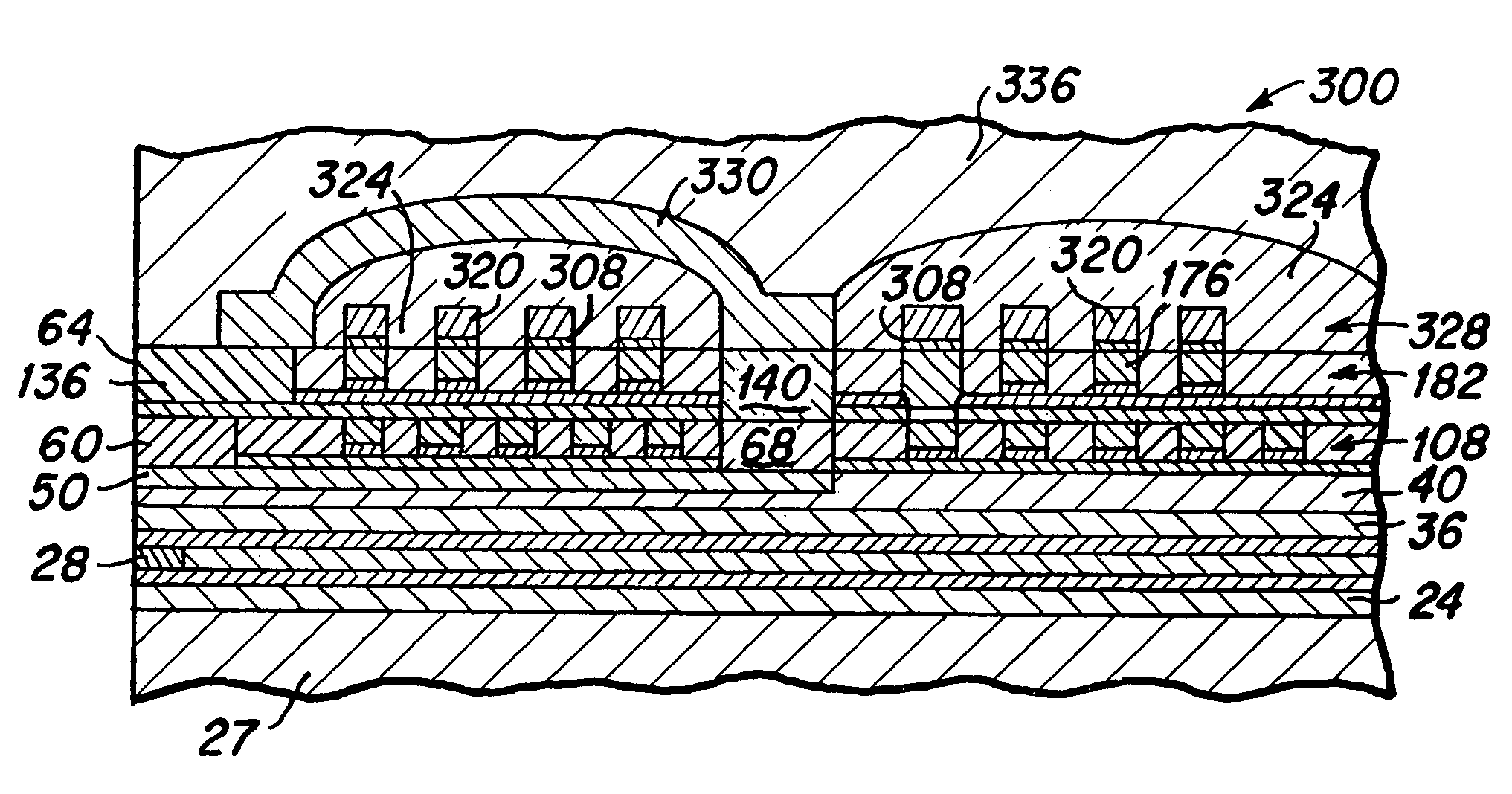
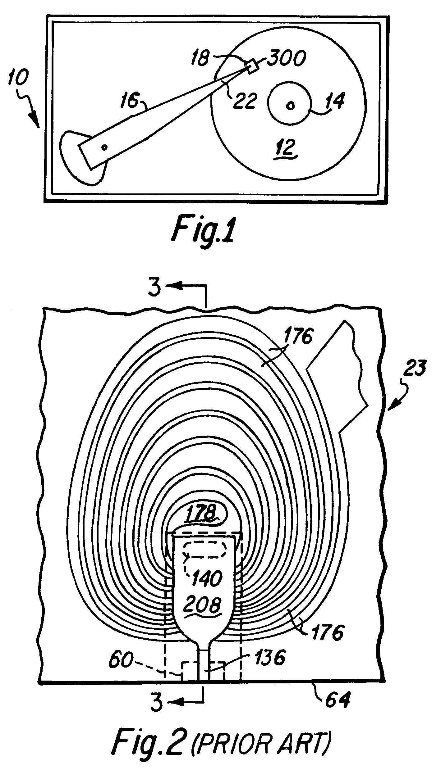
[0019]FIG. 1 is a top plan view that depicts significant components of a hard disk drive which includes the magnetic head of the present invention. The hard disk drive 10 includes a magnetic media hard disk 12 that is rotatably mounted upon a motorized spindle 14. An actuator arm 16 is pivotally mounted within the hard disk drive 10 and a slider 18 that includes a magnetic head 300 of the present invention is disposed upon a distal end 22 of the actuator arm 16. A typical hard disk drive 10 may include a plurality of disks 12 that are rotatably mounted upon the spindle 14 and a plurality of actuator arms 16 each having a slider 18 with an included magnetic head 300 mounted upon the distal end 22 of each of the actuator arms. As is well known to those skilled in the art, when the hard disk drive 10 is operated, the hard disk 12 rotates upon the spindle 14 and the slider 18 acts as an air bearing that is adapted for flying above the surface of the rotating disk, such that an air beari...


PUM

PropertyMeasurementUnit
thicknessaaaaaaaaaa
widthaaaaaaaaaa
widthaaaaaaaaaa

Abstract

A magnetic head including an induction coil having coil turns that are disposed between two magnetic poles of the magnetic head. The coil turns include a lower coil turn portion and an upper coil turn portion. In fabricating the induction coil, the lower coil turn portion is fabricated first, and the upper coil turn portion is fabricated directly upon the lower coil turn portion. The lower coil turn portion may be fabricated using damascene methods and the upper coil turn portion may be fabricated utilizing photolithographic methods. The lower coil turn portion and the upper coil turn portion of the induction coil turns are electrically connected, such that the thickness of the overall induction coil turns is increased. As a result, the electrical resistance of the coil turns is decreased, and heat generated in the coil is reduced.

Description

BACKGROUND OF THE INVENTION[0001]1. Field of the Invention[0002]The present invention relates generally to magnetic heads for hard disk drives, and more particularly to magnetic heads having a reduced induction coil electrical resistance and methods for the fabrication thereof.[0003]2. Description of the Prior Art[0004]It is a goal of the hard disk drive industry to develop magnetic heads that provide ever faster data writing speeds, such that increased quantities of data can be written onto the hard disk in shorter periods of time. Magnetic heads commonly include write heads having two magnetic pole members, generally referred to as the P1 pole and the P2 pole (which typically includes a P2 pole tip and a yoke portion), and a flat, spiral induction coil that is fabricated between the P1 and P2 poles. Write head electrical current that passes through the induction coil creates a magnetic flux in the two magnetic pole members, and the magnetic flux passes through the write head pole ...

Claims


Application Information

Patent Timeline
Patent Type & Authority Patents(United States)
IPC IPC(8): G11B5/17
CPCG11B5/17G11B5/3106G11B5/3163G11B5/3136G11B5/3123
Inventor LEE, EDWARD HIN PONGNIKITIN, VLADIMIR
Owner WESTERN DIGITAL TECH INC
Why Eureka
Try Eureka