Wide-angle imaging lens

a wide-angle imaging and lens technology, applied in the field of wide-angle imaging lenses, can solve the problems of affecting the service life of the lens, so as to achieve the effect of reducing the price and ensuring the service li

Inactive Publication Date: 2009-12-22
FUJI PHOTO OPTICAL CO LTD
View PDF10 Cites 17 Cited by
  • Summary
  • Abstract
  • Description
  • Claims
  • Application Information

AI Technical Summary

Benefits of technology

[0015]For the wide-angle imaging lens of this invention, only a comparatively small number of lenses, i.e., with a four-component, four-element construction, is employed to optimize the power arrangement and the lens material, and can be downsized and a wide angle of view obtained. Especially, since the first lens located nearest the object is a negative lens, this is a favorable arrangement for an increase in the angle of view, and since positive lenses are employed for all the sequential second to fourth lenses, this arrangement can reduce the total length of the lens, and is favorable for downsizing. Further, when conditional expressions (1) to (3) are satisfied, the angle of view can be increased, and an inexpensive arrangement can be easily provided wherein spherical glass lenses, for example, are employed for the entire lens.
[0016]Further, in this invention, the second preferable condition for the wide-angle imaging lens is satisfactorily employed in accordance, for example, with a requested specification. Thus, downsizing and an increase in the angle of view can be easily accomplished.
[0020]Also, for the wide-angle imaging lens of this invention, it is preferable that the first lens, the second lens, the third lens and the fourth lens all be glass lenses. Thus, compared with an arrangement that employs a plastic lens, this arrangement is adversely affected very little by temperature fluctuation during use, or by storage environments, and provides appropriately efficient service when mounted on a vehicular camera or a monitoring camera. Especially, in order to provide an inexpensive arrangement, it is preferable that spherical glass lenses be employed for the entire lens. When only spherical glass lenses are employed, the price can be lowered compared with when a molded, aspherical glass lens is employed.

Problems solved by technology

Also, because of limitations imposed by the availability of installation sites and the environments in which lenses are to be used, lenses that are in great demand are those that are little affected, while in use, by temperature variations (those lenses for which the number of temperature induced optical performance changes, such as altered focal points, is extremely small).
However, when plastic lenses are employed, as in Japanese Patent No. 3,437,004, an adverse effect may be produced by temperature fluctuation while the lenses are in use (a temperature fluctuation may produce a change in the optical performance, such as an altered focal point) or the lenses may be adversely affected by the environment in which they are stored (their shapes may be changed by a load imposed under high temperature).
In the event, however, were an aspherical lens to be employed as in Japanese Patent No. 3,437,004, a molded, aspherical glass lens would be required, and the cost would be increased.
However, the lens arrangement used in both JP-A-5-264895 and JP-A-10-39207 is not appropriate for a reduction in the size of an image pickup apparatus, because using the lenses to obtain an appropriate backfocus extension is one of the objectives.
The lens in JP-A-10-39207 provides an angle of view of only about 60°, and while the overall length is comparatively short, the lens is not a satisfactory means for increasing the angle of view.
As for the lens described in Japanese Patent No. 3,437,004, not only is there a problem associated with the cost of the lens material, but also the angle of view is only about 64°, and is not, therefore, a satisfactory means for increasing the angle of view.
Moreover, according to JP-A-5-264895, JP-A-10-39207 and Japanese Patent No. 3,437,004, the space between the second lens and the third lens is comparatively large, and this is also an unfavorable condition for the downsizing of an apparatus.

Method used


Image

  • Wide-angle imaging lens
  • Wide-angle imaging lens
  • Wide-angle imaging lens

Examples


examples

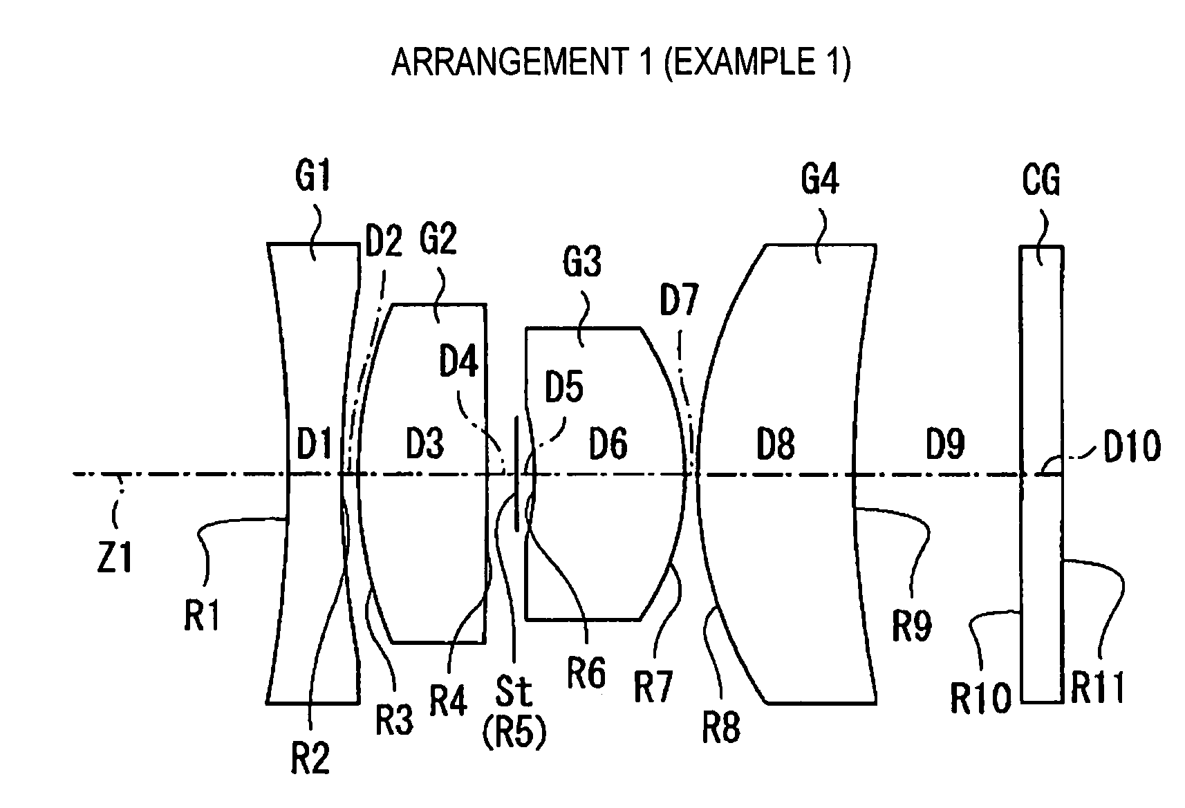
[0061]Examples 1 to 10 for providing numerical values for the wide-angle imaging lens of this embodiment will be summarized, while employing example 1 as a base.

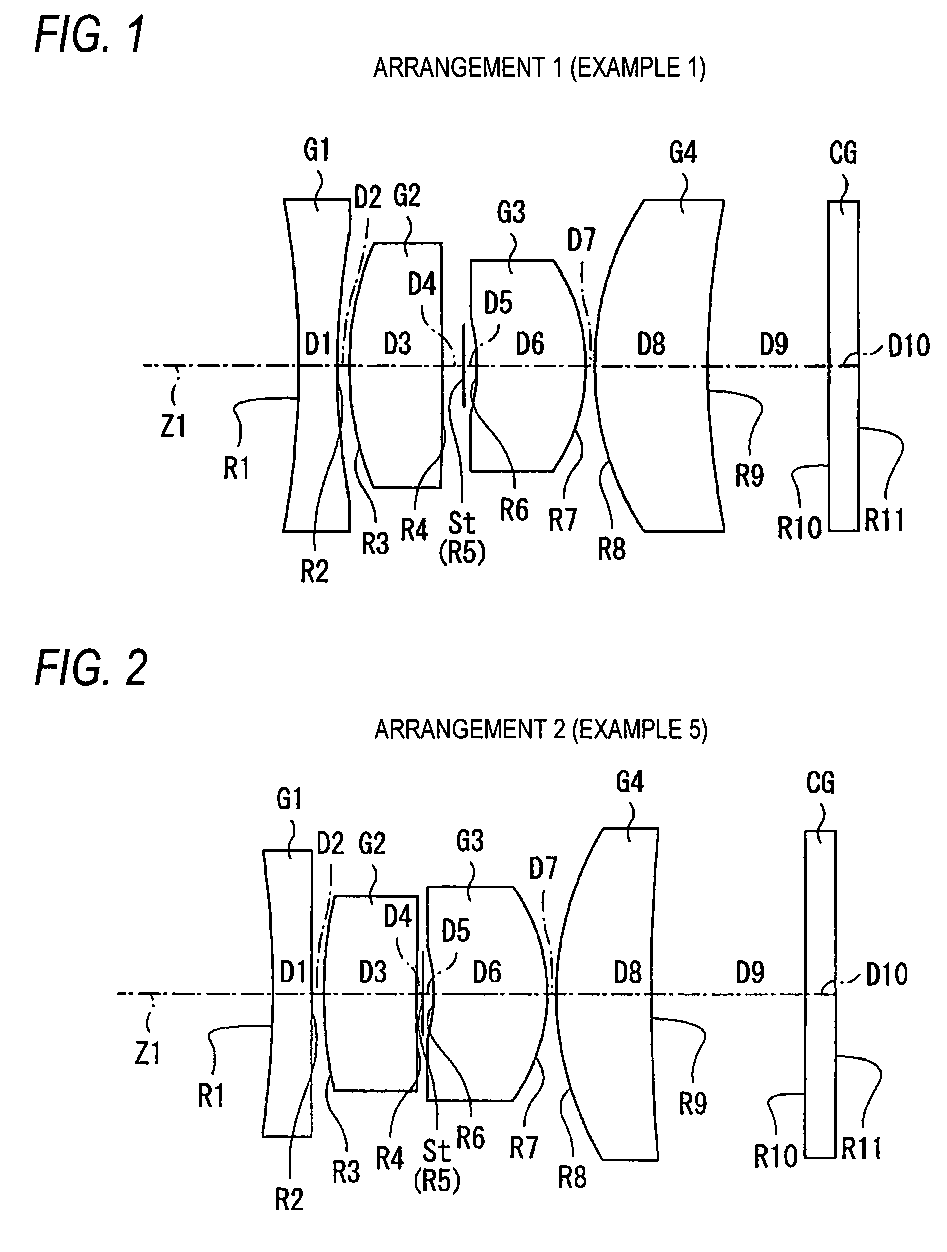
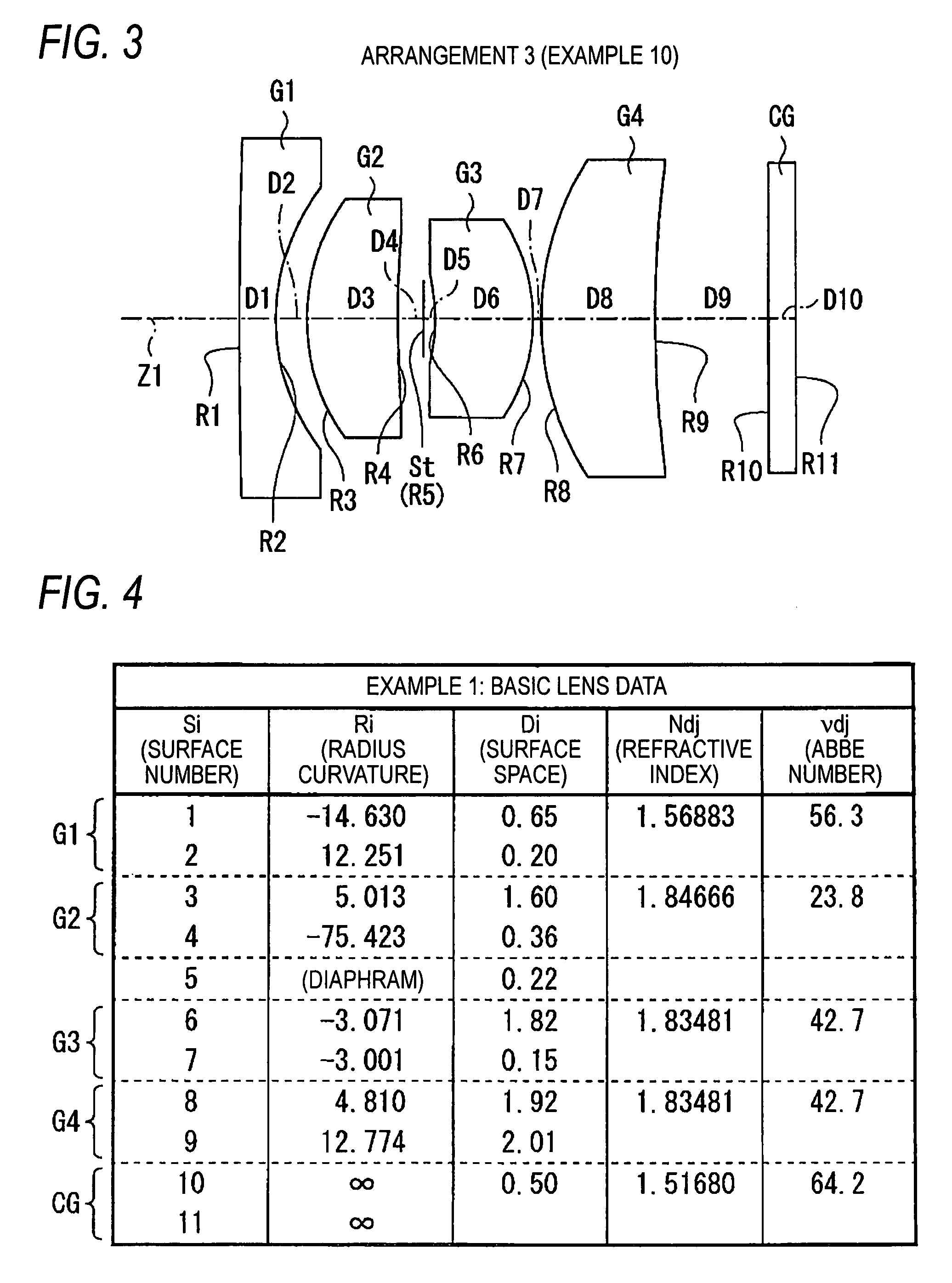
[0062]As example 1, the basic lens data, correlated with the arrangement of the wide-angle imaging lens shown in FIG. 1, is shown in FIG. 4. A number provided for a surface of a component is entered in a surface number Si lens data column shown in FIG. 4. This number is gradually incremented toward an image, while the number for the surface of a component located nearest an object is defined as 1. A value (mm) for the curvature radius of the i-th component surface from the object is entered in a curvature radius Ri column, in consonance with Ri in FIG. 1. Likewise, space (mm) on the light axis between the i-th surface Si and the (i+1)-th surface Si+1 from the object is entered in surface space Di, in consonance with Di in FIG. 1. In a refractive index Ndj column, a refractive index is entered at d-line (wavelength 587.6 nm) ...


PUM


Abstract

A wide-angle imaging lens comprises, in order from an object:a first lens having a negative refractive power;a second lens having a positive refractive power with a convex face directed to the object;an aperture diaphragm;a third lens having a positive refractive power with a convex face directed to an image; anda fourth lens having a positive refractive power with a convex face directed to the object,wherein the following conditional expressions are satisfied.N2≧1.7  (1)N3≧1.7  (2)N4≧1.7  (3)whenN2: a refractive index of the second lens at the d-lineN3: a refractive index of the third lens at the d-lineN4: a refractive index of the fourth lens at the d-line.

Description

BACKGROUND OF THE INVENTION[0001]1. Field of the Invention[0002]The present invention relates to a wide-angle imaging lens appropriate for a small, image pickup apparatus, such as a monitoring camera or a vehicular camera.[0003]2. Description of the Related Art[0004]Image pickup apparatuses, digital still cameras and video cameras that employ image sensors such as CCDs (Charge Coupled Devices) or CMOSs (Complementary Metal Oxide Semiconductors), have become popular, and accompanying this popularity is an ever growing demand for apparatuses that are smaller and less expensive, yet provide improved performance. Further, especially desired, for vehicular cameras and area monitoring cameras, are wide-angle lenses that provide a broad viewing range. Also, because of limitations imposed by the availability of installation sites and the environments in which lenses are to be used, lenses that are in great demand are those that are little affected, while in use, by temperature variations (t...

Claims


Application Information

Patent Timeline
Patent Type & Authority Patents(United States)
IPC IPC(8): G02B9/34
CPCG02B9/34G02B13/04G02B13/005
Inventor YAMAMOTO, YOKO
Owner FUJI PHOTO OPTICAL CO LTD
Why Eureka
Try Eureka