Exhaust-gas turbocharger for an internal combustion engine

a technology of exhaust gas and turbocharger, which is applied in the direction of machines/engines, mechanical equipment, transportation and packaging, etc., can solve the problems of more expensive die parts, and achieve the effects of compact overall design, reduced mechanical and thermal requirements of precision casting guide vane grids, and increased flow speed

Inactive Publication Date: 2009-12-29
DAIMLER AG
View PDF24 Cites 66 Cited by
  • Summary
  • Abstract
  • Description
  • Claims
  • Application Information

AI Technical Summary

Benefits of technology

[0006]The exhaust-gas turbocharger according to the invention, is equipped with a flow adjusting device comprising a rotary slide valve disposed in a rotary slide valve housing with a first and a second rotary slide valve housing opening, and a bypass with a bypass inlet and a bypass outlet, a first and a second flow channel of the rotary slide valve penetrating the rotary slide transversely with respect to its rotational axis. A third flow channel extends partially through the rotary slide in the direction of the rotational axis and has at least two inlet openings on the housing side and at least one outlet opening at the axial end face thereof. The inlet openings can be brought into congruence with the first and the second rotary slide housing openings. The rotary slide housing has two radial rotary slide housing openings at the side thereof which faces away from the turbine wheel, that is, a first and a second rotary slide housing opening, and three rotary slide housing openings at the side thereof which faces the turbine wheel, that is, a third, a fourth and a fifth rotary slide housing opening. When the bypass is closed, the first and the second rotary slide housing openings and the third and the fourth rotary slide housing openings correspond with the first and the second flow channels of the rotary slide, respectively. When the bypass is open, the first and the second rotary slide housing openings coincide with the inlet openings which are arranged at the end face of the rotary slide, and the outlet opening of the third flow channel of the rotary slide corresponds with the bypass inlet. As a result of the above-described arrangement, all of the exhaust gas can flow into the turbine wheel while swirl the swirl and flow speed are increased during an engine braking mode, as the flow is directed through the guide vane structure in the form of discrete flows. The mechanical and thermal requirements of the precision casting guide vane grid are lowered by the flow reduction ahead of the precision casting grid. The arrangement of the channels of the rotary slide permits mechanical, reliable blocking and opening of the channels and, moreover, leads to a compact overall design.
[0007]In one advantageous embodiment of the invention, the first and the second flow channels of the rotary slide penetrate the rotary slide perpendicularly with respect to its rotational axis. As a result of this arrangement of the channels, the channel length is shortened to its minimum and the flow loss correction values which are associated with the flow are reduced.
[0008]In a refinement of the invention, the rotary slide has sealing rings and at least one sealing strip for flow guidance with virtually no losses.
[0011]In still a further advantageous refinement, the third flow channel is arranged transversely, in particularly perpendicularly with respect to the first and the second flow channels, there being a continuous wall of the rotary slide between the first or the second flow channel and the third flow channel. As a result of this arrangement, it is possible to direct the flow from at least two exhaust gas lines into a single flow channel, in a compact and reliable design.

Problems solved by technology

The turbo-brake radial flow guide structures are filigree precision casting die parts which are more expensive the higher the mechanical and thermal requirements are on account of high exhaust gas mass flows.

Method used


Image

  • Exhaust-gas turbocharger for an internal combustion engine
  • Exhaust-gas turbocharger for an internal combustion engine
  • Exhaust-gas turbocharger for an internal combustion engine

Examples


Embodiment Construction

[0022]In the figures, identical or identically acting components are provided with identical designations.

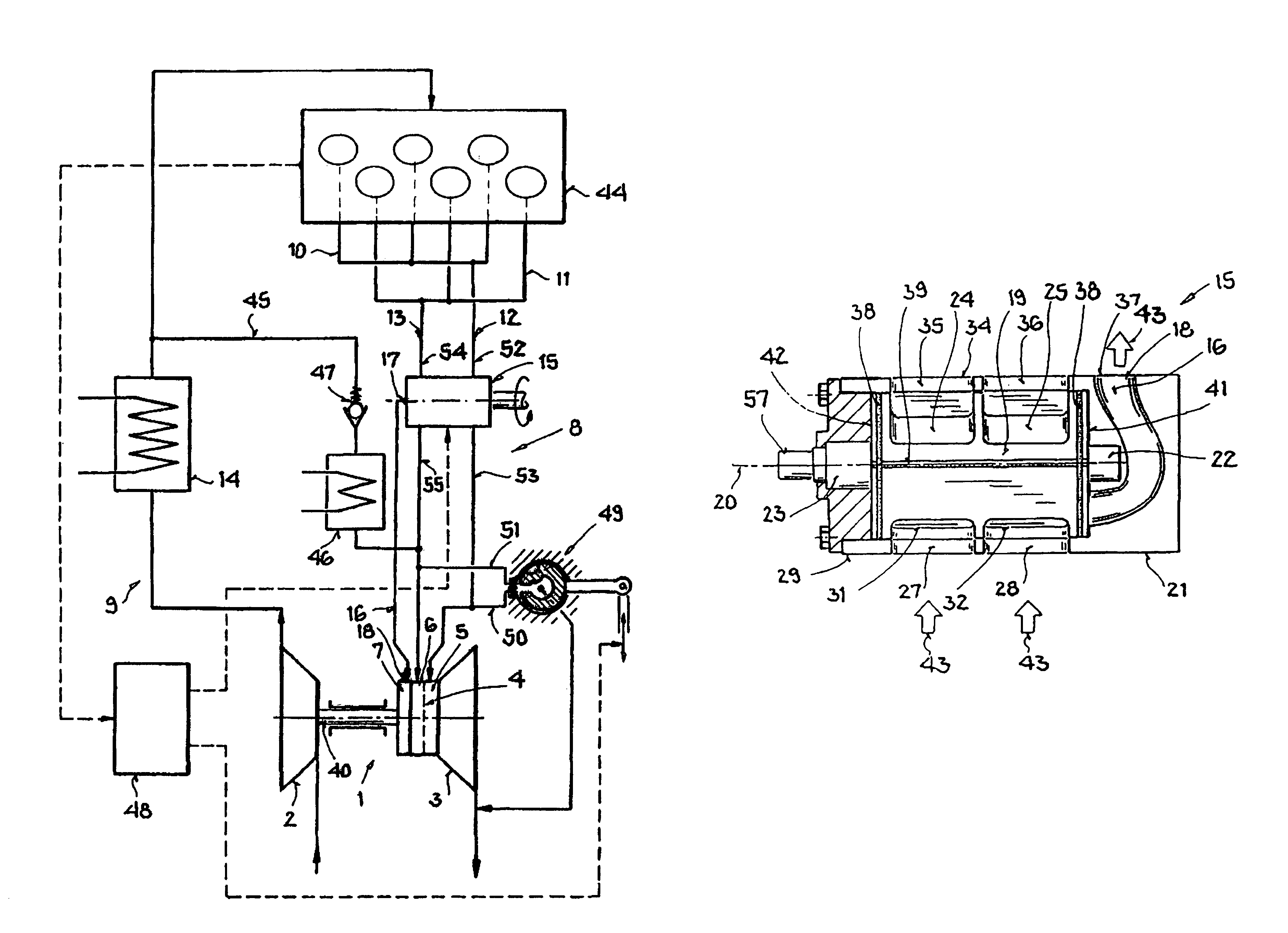
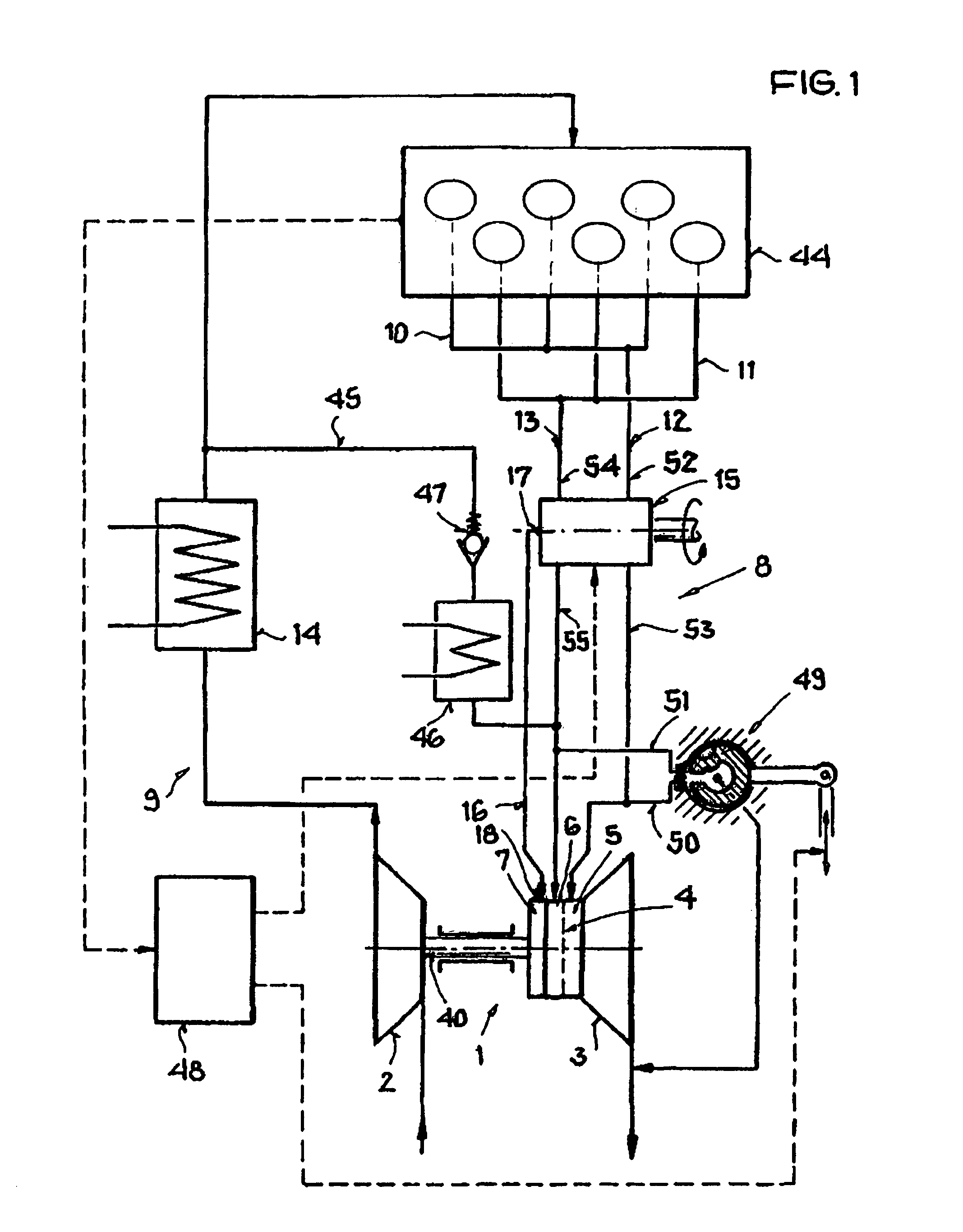
[0023]FIG. 1 shows an internal combustion engine 44, a diesel engine or a spark ignition engine, for a motor vehicle, which internal combustion engine 44 has an exhaust gas section 8 and an intake section 9. The internal combustion engine 44 includes an exhaust-gas turbocharger 1. The exhaust-gas turbocharger 1 comprises a compressor 2 which is connected fixedly in terms of rotation to a turbine 3 via a shaft 40. The turbine 3 is driven by the exhaust gas of the internal combustion engine 44 and drives the compressor 2 via the shaft 40 with the result that combustion air can be sucked in and compressed by the compressor 2. The turbine 3 has a turbine wheel 4 and three flow passages, a first flow passage 5, a second flow passage 6 and a third flow passage 7. A charge air cooler 14 for cooling the compressed combustion air is accommodated in the intake section 9 of the internal co...


PUM


Abstract

In an exhaust gas turbocharger for an internal combustion engine having air intake ducts and exhaust gas discharge ducts including a compressor and a turbine with at least two inlet flow passages, a flow adjusting device (15) arranged in the exhaust gas discharge ducts upstream of the turbine and including a rotary slide valve for controlling the exhaust gas flow first and second flow channels extending through the rotary slide, a third flow channel extends axially partially through the rotary slide valve via inlet openings at the circumference of the rotary slide which can be brought into overlapping relationship with rotary slide housing openings for controlling the exhaust gas flow from the engine to the turbine.

Description

[0001]This is a Continuation-In-Part Application of pending International Patent Application PCT / EP2005 / 011928 filed Nov. 8, 2005 and claiming the priority of German patent application 10 2004 055 571.0 filed Nov. 18, 2004.BACKGROUND OF THE INVENTION[0002]The invention relates to an exhaust-gas turbocharger for an internal combustion engine including a compressor disposed in an engine intake section and or turbine disposed in an engine exhaust section and having a plurality of exhaust gas inlet flows and a turbine bypass line and a rotary slide valve for controlling the exhaust gas flows through and past the turbine.[0003]DE 196 18 160 C2 discloses an exhaust-gas turbocharger for an internal combustion engine, the turbine of which has a rotor and a turbine housing having at least two inlet flow passages which are separated by a separating wall, and a bypass branching off from at least one flow passage. Exhaust gas can be conducted away from at least one flow passage via this bypass....

Claims


Application Information

Patent Timeline
Patent Type & Authority Patents(United States)
IPC IPC(8): F02D23/00F02B37/18F02B37/22F02B37/00F16K11/085F02C6/12
CPCF02B37/025F02B37/183F02B37/22Y10T137/86871Y02T10/12
Inventor HERTWECK, GERNOTHIRTH, TORSTENKRÄTSCHMER, STEPHANLÖFFLER, PAULSUMSER, SIEGFRIED
Owner DAIMLER AG
Why Eureka
Try Eureka