Compound bow

a compound bow and cam technology, applied in the field of compound bows, can solve the problems of inability to repair or replace the first and second, and the user is restricted in the use of the compound bow, so as to facilitate maintenance and easy replacement of parts of the bow. , the effect of preventing the dislocation of the cam

Inactive Publication Date: 2009-12-29
LEE SEUL KI
View PDF5 Cites 63 Cited by
  • Summary
  • Abstract
  • Description
  • Claims
  • Application Information

AI Technical Summary

Benefits of technology

[0015]Accordingly, the present invention has been made to solve the above-mentioned problems occurring in the prior art, and an object of the present invention is to provide a compound bow in which a cable connected between an upper wing and a lower wing is removed, the distortion of a cam is prevented, thereby facilitating maintenance and ease of replacement of parts of the bow.

Problems solved by technology

However, in the case where the compound bow is used is a plain and the first and second cables 40 and 46, or the bow string 50 should be repaired or replaced, problems arise in that it is impossible to repair or replace the first and second cables 40 and 46, and the bow string 50 without the pool bow press, and that if one carried the pool bow press with him, he is restricted in movement in using the compound bow.

Method used


Image

  • Compound bow
  • Compound bow
  • Compound bow

Examples


second embodiment

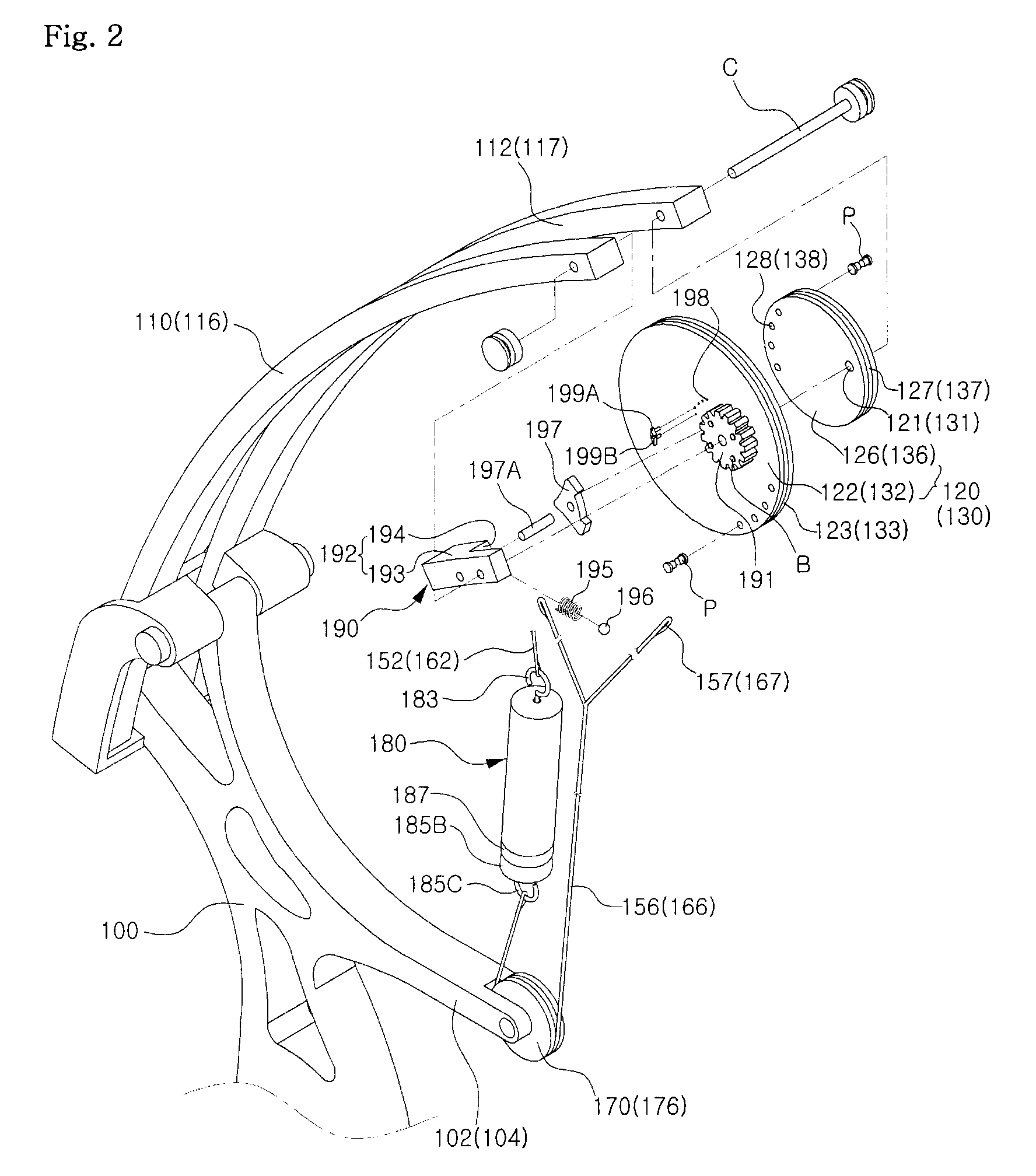
[0081]FIG. 10 is an exploded perspective view of main parts of a compound bow according to the invention, and FIG. 11 is a partial enlarged side view illustrating a state in which a ratchet member is coupled to rotating units and wing units in FIG. 10.

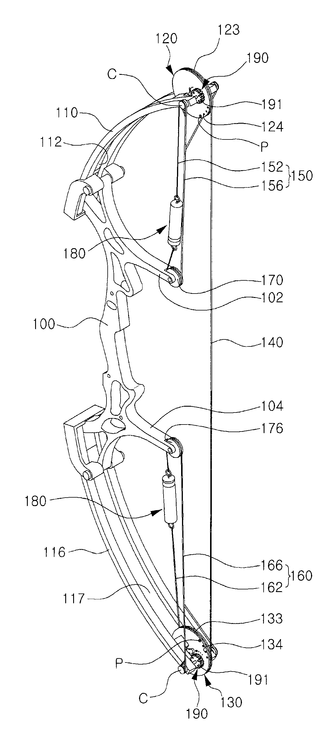
[0082]The compound bow according to the second embodiment includes a handle 100, wing units, rotating units, a bow string 140, a cable member, a tensioner member 180, and a ratchet member 190. Detailed description thereof will be made of only the modified construction other than the same construction as above-mentioned first embodiment. The reference numerals to be hereinafter used are the same as those of the first embodiment.

[0083]As shown in FIGS. 10 and 11, the ratchet member 190 is installed on the upper and lower cam members 120 and 130 and the upper and lower wings 110 and 116, such that, upon pulling the bow string 140, the upper and lower cam members 120 and 130 are prevented from being restored, and that the bow string 140 is...

third embodiment

[0100]FIG. 13 is a perspective view of a compound bow according to the invention. A plurality of fixing portions 202 and 204 protrudes outside from one face of a handle 200. A plurality of upper / lower cam members 220 and 230 is installed on a pair of upper / lower wings 210 and 216 longitudinally coupled to both ends of the handle 200. A bow string 240 is connected between the upper and lower cam members 220 and 230, and a plurality of upper and lower cables 250 and 260 turning about by pulleys 270 and 276 is connected to the upper and lower wings 210 and 216. A ratchet member 290 is installed on the upper / lower cam members 220 and 230 and the upper / lower wings 210 and 216, and a tensioner member 280 for adjusting an angle of the upper / lower cam members 220 and 230 and intensity of the bow is installed on the upper / lower cables 250 and 260.

first embodiment

[0101]The operation of the above-mentioned construction is the same as that of the first embodiment, and the above construction has advantages in that a plurality of arrows can be used at the same time, and that the hunt can be completed quickly, particularly on a plane.

[0102]While the third embodiment has illustrated that two arrows can be used at the same time, the present invention is not limited thereto, but may shoot three or more arrows according to the use purpose and the size of the compound bow.

[0103]As set forth before, the compound bow according to the present invention has effects to improve the shooting accuracy of an arrow with removal of the cable passing by the bow string, to extend the lifetime of the compound bow with the prevention of distortion in the upper / lower cam members and the upper / lower wings, to provide a strong bow and to safely use the bow with the prevention of restoration of the bow string and the upper / lower cam members upon pulling the bow string w...


PUM


Abstract

Compound bow in which a cable interfering with advance of an arrow is removed to improve shooting accuracy of the arrow, to prevent the distortion of the bow, and to simply manipulate equipment of the bow. The compound bow comprises: handle having fixing portions protruding from one surface thereof; wing units coupled to both ends of the handle; rotating units rotatably coupled to free ends of the wing units, respectively, by an eccentric shaft; a bow string connected between the respective rotating units; a pulley shaft-coupled to the fixing portion of the handle; cable members each having one end connected to each rotating unit and the other end connected to the free end of each wing unit via the pulley. Optionally tensioner member may be installed on one side of each cable member and ratchet member may be installed on the respective rotating units and wing units.

Description

BACKGROUND OF THE INVENTION[0001]1. Field of the Invention[0002]The present invention relates to a compound bow, and more particularly to a compound bow in which a cable connected between an upper wing and a lower wing is removed, and the distortion of a cam is prevented, thereby facilitating maintenance and ease of replacement of parts of the bow.[0003]2. Description of the Prior Art[0004]As generally known in the art, a compound bow is one generally used for hunting which, upon pulling, is easily drawn using a roller type cam or wheel without applying a large force, and upon shooting, increases a shooting force about two times to thereby speed up an arrow with great force.[0005]FIG. 14 is a perspective view of a compound bow according to the prior art, FIG. 15 is a bottom view of a compound bow according to the prior art, and FIG. 16 is a partial enlarged perspective view of a prior compound bow in which a cam thereof is in a distorted state.[0006]As shown in FIGS. 14 to 16, the c...

Claims


Application Information

Patent Timeline
Patent Type & Authority Patents(United States)
IPC IPC(8): F41B5/10
CPCF41B5/105F41B5/10A47G9/1009A61G17/044
Inventor LEE, SEUL-KI
Owner LEE SEUL KI
Why Eureka
Try Eureka