

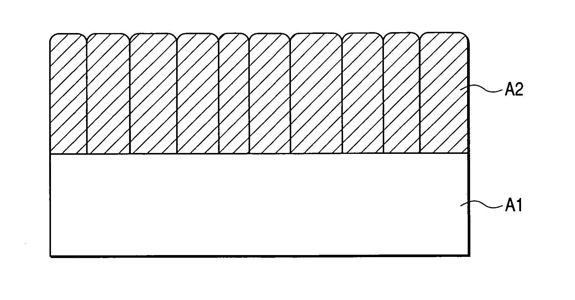
Semiconductor and semiconductor manufacturing arrangements having a chalcogenide layer formed of columnar crystal grains perpendicular to a main substrate surface
a technology of chalcogenide layer and semiconductor, which is applied in the direction of instruments, vacuum evaporation coating, coating, etc., can solve the problems of unsuitable large-capacity memory, high access speed of sram, low access speed of dram, etc., and achieve the reduction of non-uniform electrical characteristics and reliability deterioration, and the effect of reducing the non-uniform characteristics of elements due to a large crystal grain siz
- Summary
- Abstract
- Description
- Claims
- Application Information
AI Technical Summary
Benefits of technology
Problems solved by technology
Method used
Image

Examples
embodiments
[0102]Embodiments of the present invention are described in detail below in accordance with the accompanying drawings.
first embodiment
[0103]A first embodiment of the present invention is described below with reference to FIGS. 13 and 14. This embodiment intends to suppress a growth of inclined crystal grains by forming a chalcogenide layer under the conditions that render the chalcogenide layer amorphous and is an example in which first means for forming phase change memory cells in a semiconductor storage device of the present invention is shown in detail.
[0104]As shown in FIG. 13, a semiconductor substrate A101 is prepared for use and an MOS transistor for use as a select transistor is produced. To this end, an inter-element isolation oxide film A102 for isolating the MOS transistor is first formed on the surface of the semiconductor substrate A101 by using a well-known selective deposition method or trench isolation method. The present embodiment employs the trench isolation method that allows surface planarization.
[0105]First, an isolation trench is formed in the substrate by using a well-known dry-etching met...
second embodiment
[0125]A second embodiment of the present invention is described below with reference to FIGS. 13 and 14. This embodiment intends to suppress a growth of inclined crystal grains by post-annealing a chalcogenide layer and forming an “fcc” crystal of a columnar structure, and is an example in which the second means for forming phase change memory cells in the above-mentioned semiconductor storage device of the present invention is shown in detail.
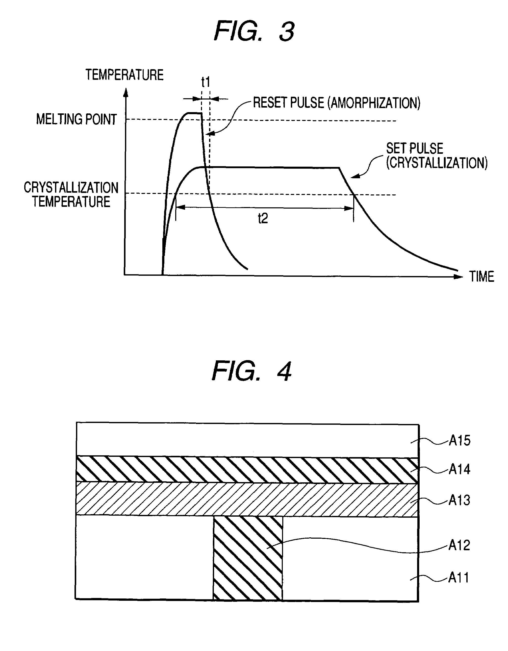
[0126]The description of FIG. 13 is omitted since processes up to forming a tungsten plug A112 are the same as in the first embodiment. After the formation of the plug A112, a chalcogenide layer A113 formed of a 100-nm-thick GeSbTe film in an amorphous phase is deposited using a sputtering method.
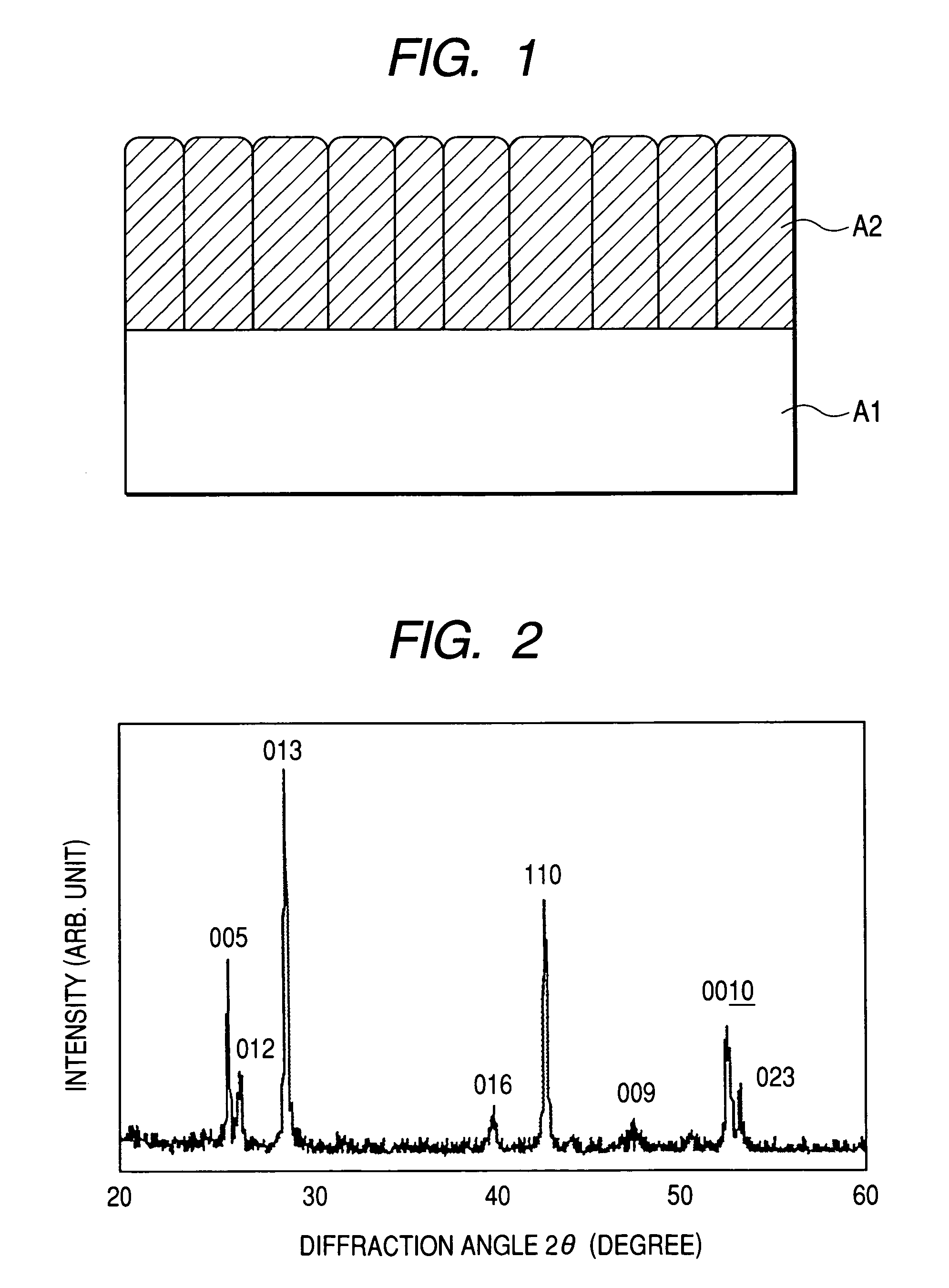
[0127]The deposition is followed by 200° C. three-minute annealing in an argon (Ar) atmosphere. This annealing process forms GeSbTe into such an “fcc” crystal of a columnar structure as shown in FIG. 11. A temperature of 100° C. or more and up to 400°...
PUM
| Property | Measurement | Unit |
|---|---|---|
| melting point | aaaaa | aaaaa |
| thickness | aaaaa | aaaaa |
| temperature | aaaaa | aaaaa |
Abstract
Description
Claims
Application Information