Rotor of rotary-electric machine

a rotary-electric machine and rotor technology, which is applied in the direction of windings, magnetic circuit rotating parts, magnetic circuit shapes/forms/construction, etc., can solve the problems of insufficient cooling performance of the rotor winding and inability to efficiently reduce the temperature of each slot, so as to improve the cooling performance of the rotor winding and the effect of efficient introduction of cooling air

Active Publication Date: 2009-12-29
MITSUBISHI HEAVY IND LTD
View PDF6 Cites 4 Cited by
  • Summary
  • Abstract
  • Description
  • Claims
  • Application Information

AI Technical Summary

Benefits of technology

[0013]The present invention has been developed in view of the above problem, and an object is to provide a rotor of a rotary-electric machine in which a cooling performance of a rotor winding has been improved.
[0015]In the rotor of the rotary-electric machine according to the present invention, the cooling air can be introduced into the conductors constituting the rotor winding from the openings of the air inlet holes disposed in the bottoms of the conductors on the side opposite to the side on which the ventilation channels are formed. Therefore, regardless of an air inlet angle of the cooling air, the cooling air can efficiently be introduced. There is an advantage that a temperature rise of the conductors is inhibited to improve a cooling performance of the rotor winding.
[0016]An object to improve the cooling performance of the rotor winding is realized with a simple constitution without involving any large structural change.

Problems solved by technology

However, in the above conventional technology (JP-A-63-15644), a temperature of each slot cannot necessarily be lowered efficiently.
As a result, the temperature is raised without effectively cooling the conductors, and this results in a problem that a cooling performance of the rotor winding is not satisfactory.

Method used


Image

  • Rotor of rotary-electric machine
  • Rotor of rotary-electric machine
  • Rotor of rotary-electric machine

Examples


embodiment 1

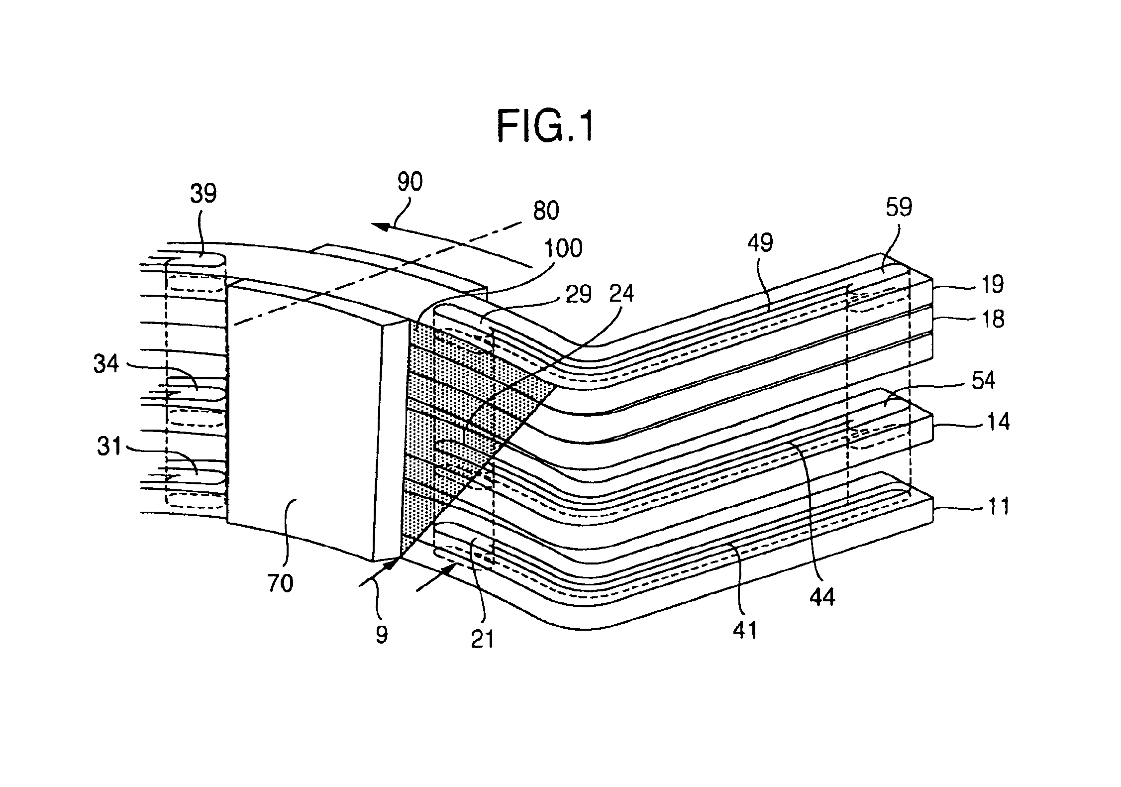
[0028][Embodiment 1]

[0029]A structure of a turbine generator is shown in FIGS. 7 and 8.

[0030]As shown, the turbine generator is generally constituted by disposing a rotor 4 supported by a rotation shaft 2 so that the rotor faces a stator 5. A rotor iron core 4a constituting the rotor 4 extends in an axial direction, and has a plurality of slots 6 formed at predetermined intervals in a peripheral direction. In the slots 6, a plurality of conductors 1 forming a rotor winding are laminated and stored. The conductors 1 are bound to the rotor iron core 4a by wedges 7 disposed on outer peripheral sides of the slots 6, and the wedges 7 are designed so as to hold the conductors 1 even during rotation at a high speed. A retaining ring 3 is fixedly fitted into an end portion of the rotor winding in the axial direction via an insulating cylinder so as to cover the end portion, and this retaining ring 3 retains a centrifugal force of the conductors 1.

[0031]Additionally, in general, there is not...

embodiment 2

[0038][Embodiment 2]

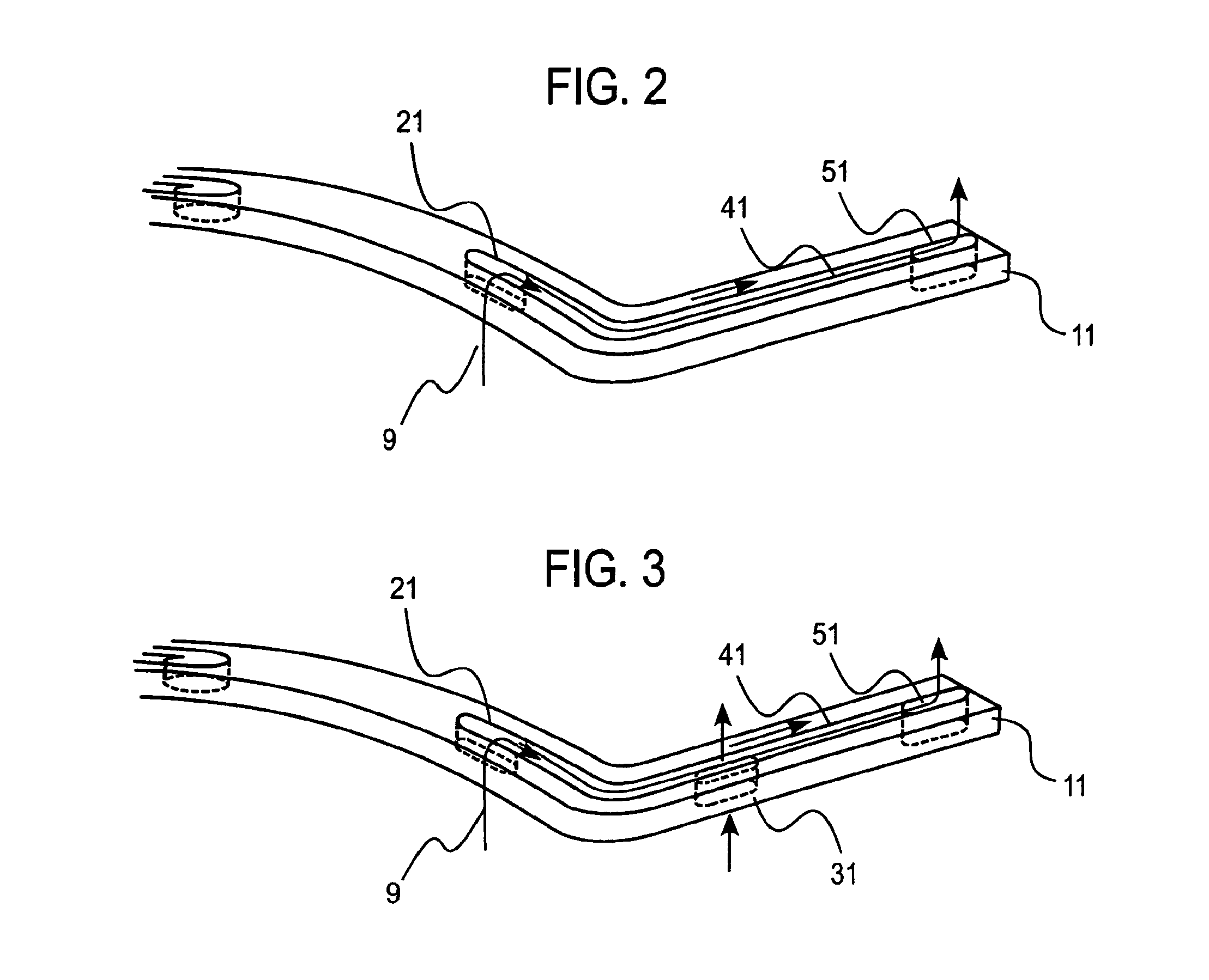
[0039]FIG. 3 shows another example of a conductor employed in a rotor winding according to the present invention. In the shown example, in a middle of a ventilation channel 41 of a conductor 11 shown in FIG. 2, a second air inlet hole 31 is disposed in a bottom of the conductor on a side opposite to a side on which the ventilation channel 41 is formed. A plurality of conductors formed in such a manner are laminated in a diametric direction to constitute a rotor winding.

[0040]Even with such a constitution, needless to say, the above-described effect is achieved. Moreover, since a plurality of air inlet holes are disposed, a temperature distribution of the conductors in a longitudinal direction can arbitrarily be changed.

[0041]FIG. 4 shows an example of a temperature rise in the position of each conductor in the longitudinal direction in a case where the conductor in FIG. 3 is used, the abscissa indicates the position of the conductor in the longitudinal direction,...

embodiment 3

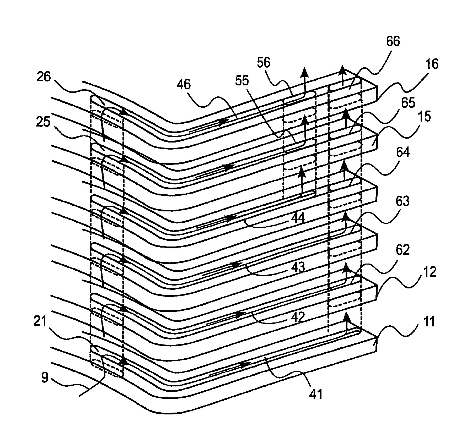
[0043][Embodiment 3]

[0044]FIG. 5 shows a third embodiment of the present invention. In this embodiment, openings of air inlet holes 21 to 26 are disposed in bottoms of conductors on a side opposite to a side on which ventilation channels 41 to 46 are formed. Moreover, the air inlet holes continuously extend in a diametric direction to communicate with end portions of the ventilation channels 41 to 46 formed in the surfaces of the conductors along a peripheral direction. Furthermore, in axial-direction end portions of the ventilation channels 41 to 46 formed in the surfaces of conductors 11 to 16 along an axial direction, the end portion in a lower part (conductors 11 to 13) of a rotor winding in a laminating direction of the conductors 11 to 16 is formed to extend longer than that in an upper part (conductors 14 to 16) of the rotor winding. As to exhaust holes which exhaust cooling air 9 flowing through the ventilation channels 41 to 46, there is formed a path (exhaust holes 55, 56)...


PUM


Abstract

In a rotor of a rotary-electric machine, in order to improve a cooling performance of a rotor winding, in a rotor winding on an end portion of the rotor in an axial direction, the rotor winding being held by a retaining ring of the rotor winding formed by laminating a plurality of conductors in slots of a rotor iron core extending in an axial direction and having a plurality of slots formed at predetermined intervals in a peripheral direction, ventilation channels through which cooling air flows are formed in the surfaces of the conductors along a longitudinal direction. The ventilation channels have air inlet holes which guide the cooling air and exhaust holes which exhaust the cooling air, the conductors provided with the ventilation channels which are formed in the surfaces of the conductors along the longitudinal direction and through which the cooling air flows are laminated to constitute the rotor winding, and the conductors include openings of the air inlet holes in bottoms of the conductors on a side opposite to a side on which the ventilation channels are formed.

Description

BACKGROUND OF THE INVENTION[0001]1. Field of the Invention[0002]The present invention relates to a rotor of a rotary-electric machine, more particularly to a rotor of a rotary-electric machine suitable as, for example, a rotor of a turbine generator in which ventilation channels for cooling air are formed in conductors constituting a rotor winding on an end portion of the rotor in an axial direction.[0003]2. Description of the Related Art[0004]A general turbine generator is generally constituted by disposing a rotor supported on a rotation shaft so that the rotor faces a stator. A rotor iron core constituting the rotor extends in an axial direction and has a plurality of slots formed at predetermined intervals in a peripheral direction, and a plurality of conductors forming a rotor winding are laminated and stored in the slots. The conductors are bound by wedges disposed on outer peripheries of the slots, and the wedges are designed so as to hold the conductors even during rotation ...

Claims


Application Information

Patent Timeline
Patent Type & Authority Patents(United States)
IPC IPC(8): H02K3/04H02K3/24H02K9/00
CPCH02K3/24
Inventor HATTORI, KENICHISAEKI, MITSURUSEMBA, AKITOMIKAKIMOTO, TADAAKIWATANABE, TAKASHISUZUKI, MANABUSHIBATA, TAKASHIMURAMATSU, SEIJIRO
Owner MITSUBISHI HEAVY IND LTD
Why Eureka
Try Eureka