X-ray tool for an oilfield fluid

a technology for oilfield fluids and x-ray tools, which is applied in the direction of instruments, nuclear engineering, and handling using diaphragms/collimeters, etc., which can solve the problems of significant radiation exposure risk for users, substantial compromise of the mobility of the radioactive densitometer assembly, and failure of a portion of the shielding

Inactive Publication Date: 2009-12-29
SCHLUMBERGER TECH CORP
View PDF19 Cites 19 Cited by
  • Summary
  • Abstract
  • Description
  • Claims
  • Application Information

AI Technical Summary

Problems solved by technology

Unfortunately, radioactive densitometers as described above involve the use of hazardous radioactive material on site.
The densitometers must be manually positioned and employed in a hands-on manner subjecting users to significant risk of exposure to dangerous levels of radiation.
As a result, the mobility of the radioactive densitometer assembly is substantially compromised.
Furthermore, there remains the possibility of failure of a portion of the shielding which, even if only to a minimal degree, may pose very significant health risks to anyone on site.
Nevertheless, during operation the x-ray densitometer may emit a significant amount of lower energy, but still potentially hazardous x-rays.
Thus, set-up, positioning, and take down of the assembly on site remains a significant challenge to the user.

Method used


Image

  • X-ray tool for an oilfield fluid
  • X-ray tool for an oilfield fluid
  • X-ray tool for an oilfield fluid

Examples


Embodiment Construction

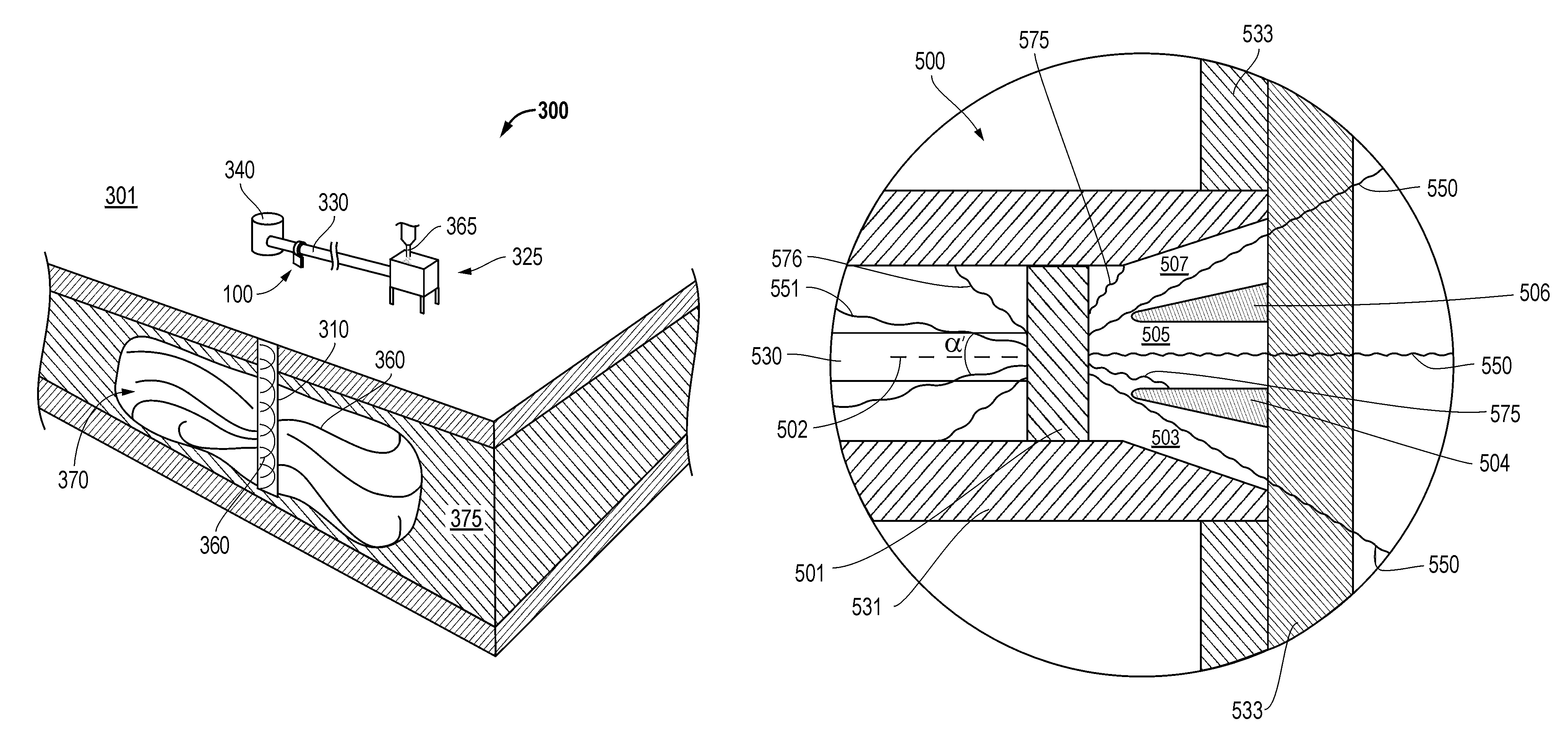
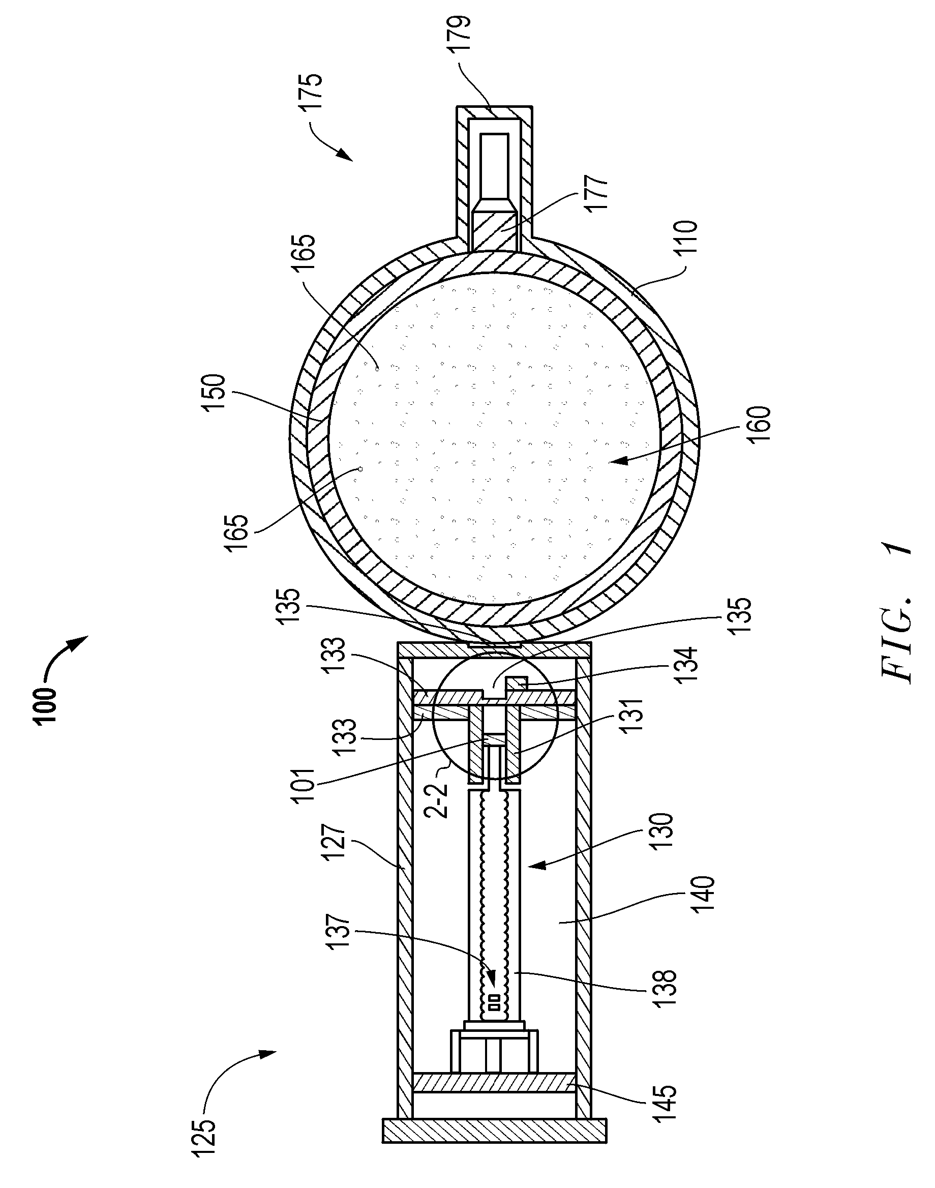
[0017]Embodiments are described with reference to certain x-ray tools for use in fracturing applications at an oilfield. However, other oilfield applications may make use of x-ray tool embodiments described herein. For example, cementing and drilling applications may employ embodiments of x-ray tools described herein. Regardless, embodiments described include x-ray tools that require no more than about 25 lbs. or less of shielding in order to be safely employed by a user. In fact, oilfield x-ray tools described below may be less than about 50 lbs. in total weight and of mobile configurations for hand-held user-friendly handling and placement at the oilfield.

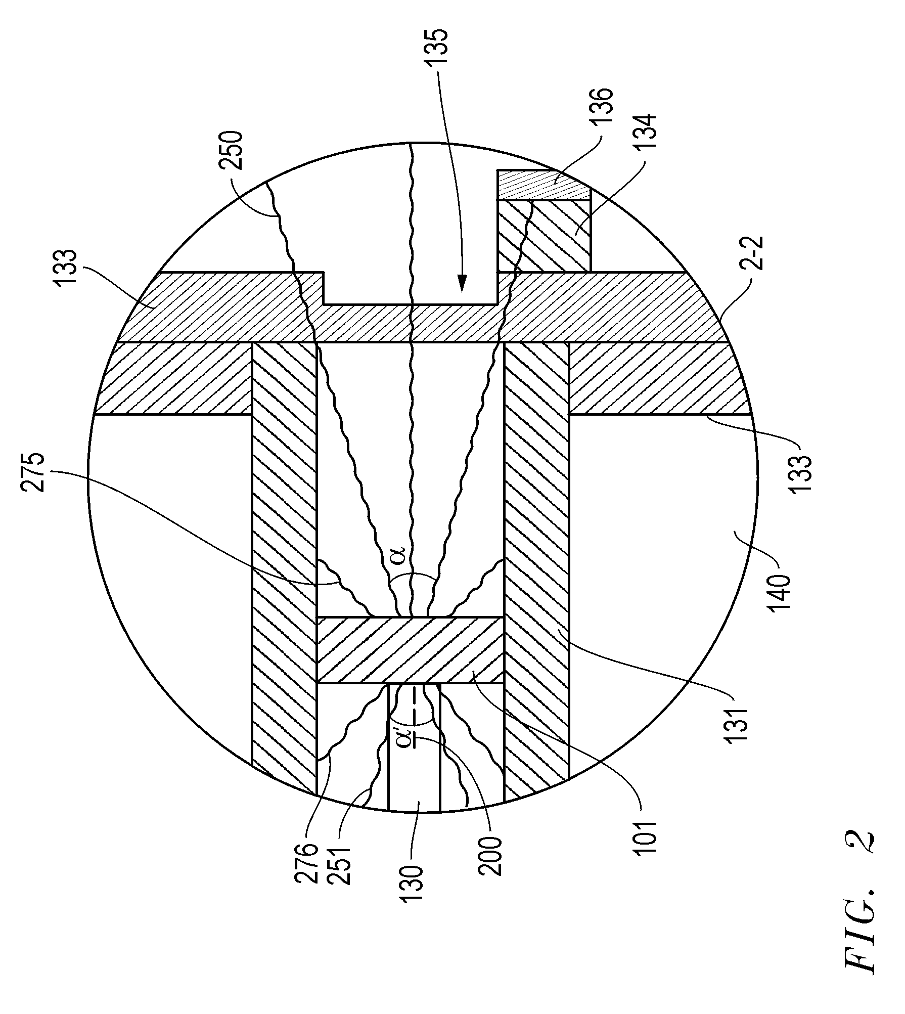
[0018]Referring now to FIG. 1 an embodiment of an oilfield x-ray tool 100 is depicted coupled to an oilfield fluid line 150. The oilfield fluid line 150 is configured to transport an oilfield fluid 160 to a well 310 at an oilfield 301 as shown in FIG. 3. In particular, the embodiment shown reveals an oilfield fluid 160 in the for...


PUM


Abstract

An x-ray tool for determining a characteristic of an oilfield fluid. The tool may include a generator portion housing a collimator about a target from which x-rays are emitted. In this manner x-rays may be attenuated right at the target such that a majority of shielding otherwise necessary for safety concerns may be eliminated. Rather, by employing the target within the collimator, shielding of the generator may be limited to a single shielding plate within the generator portion that is positioned parallel to the target at the opposite end of an x-ray tube therebetween. As a result of this configuration, an x-ray tool for analysis of oilfield fluids may be provided with a minimum weight of shielding material. Thus, hand-held user friendly embodiments may be safely employed at the oilfield.

Description

PRIORITY CLAIM[0001]This Patent Document is a Continuation-In-Part of application Ser. No. 11 / 532,236, Apparatus and Method for Well Services Fluid Evaluation Using X-Rays, filed Sep. 15, 2006. This Patent Document is also a Continuation-In-Part of application Ser. No. 11 / 751,727, X-Ray Tool For An Oilfield Fluid, filed May 22, 2007 now abandoned.BACKGROUND[0002]Embodiments described relate to tools for aiding in analysis of fluids at an oilfield. In particular, embodiments of x-ray tools that are compact and highly mobile are described.BACKGROUND OF THE RELATED ART[0003]The production of hydrocarbons from an oilfield generally involves a variety of applications employing oilfield fluids. For example, a host of large scale equipment may be delivered to an oilfield for the purpose of extracting hydrocarbons therefrom. These applications may involve the addition of oilfield fluids through a well drilled into a formation at the oilfield in order to provide access to the hydrocarbons. T...

Claims


Application Information

Patent Timeline
Patent Type & Authority Patents(United States)
IPC IPC(8): G01B15/02G01V5/12G21K1/02H01J35/08
CPCG01N23/12G01N33/2823H01J35/18G21K1/10H01J2235/18G01N23/083
Inventor SHAMPINE, RODGROVES, JOEL L.DURKOWSKI, ANTHONYVALLEE, ETIENNEWRAIGHT, PETER
Owner SCHLUMBERGER TECH CORP
Why Eureka
Try Eureka