Power supply circuitry for data signal transceivers on integrated circuits

Active Publication Date: 2009-12-29
ALTERA CORP
View PDF15 Cites 16 Cited by
  • Summary
  • Abstract
  • Description
  • Claims
  • Application Information

AI Technical Summary

Benefits of technology

[0004]In order to avoid noise contamination between various parts of data signal transceiver circuitry, a first power supply is provided for receiver path components of the circuitry, a se

Problems solved by technology

However, this can lead to a requirement for unacceptably large numbers of separate power supplies, especially for devices having large numbers of channels for high-speed serial communication.
An additional problem that may arise in inte

Method used


Image

  • Power supply circuitry for data signal transceivers on integrated circuits
  • Power supply circuitry for data signal transceivers on integrated circuits
  • Power supply circuitry for data signal transceivers on integrated circuits

Examples


Example

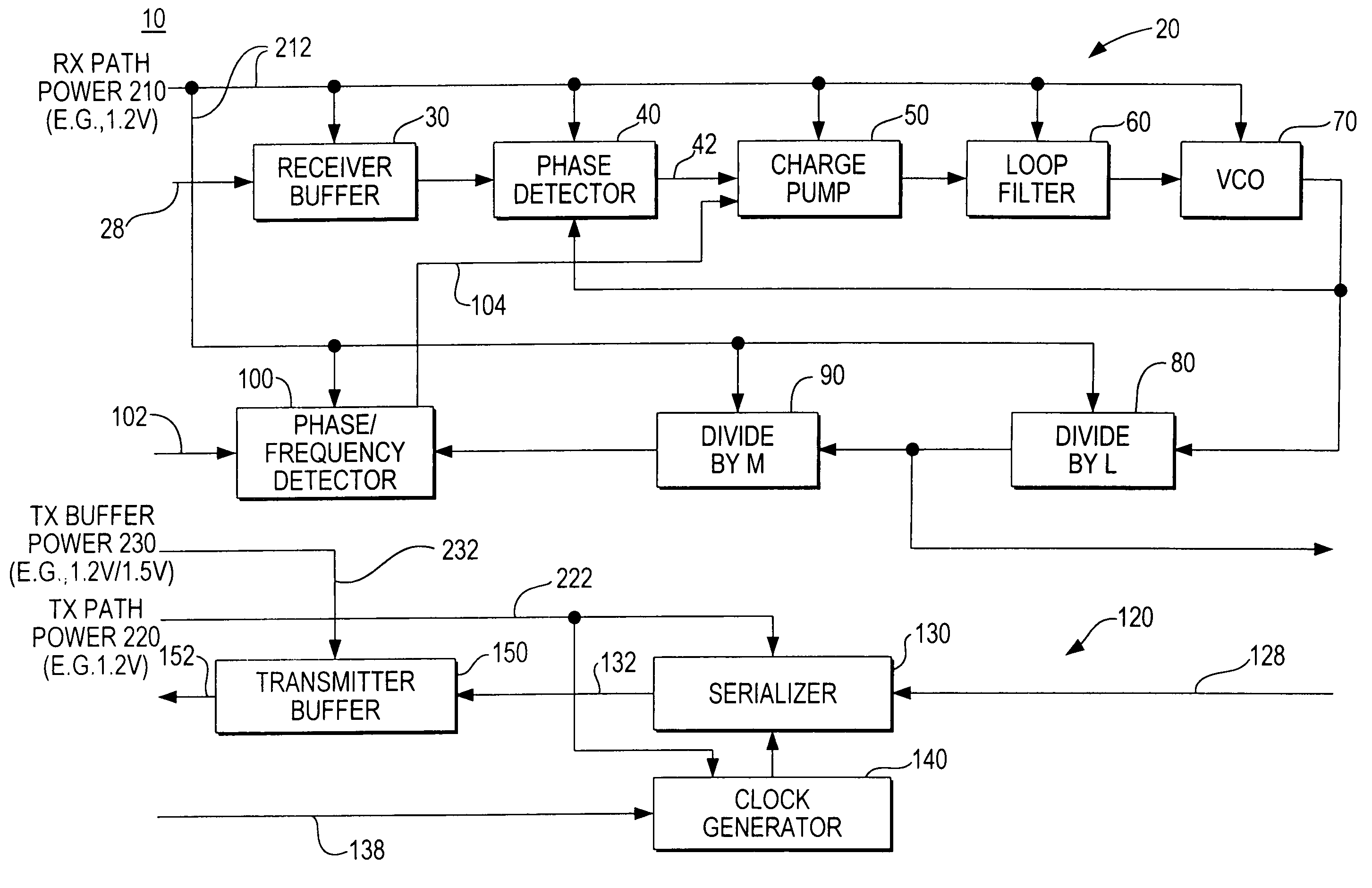
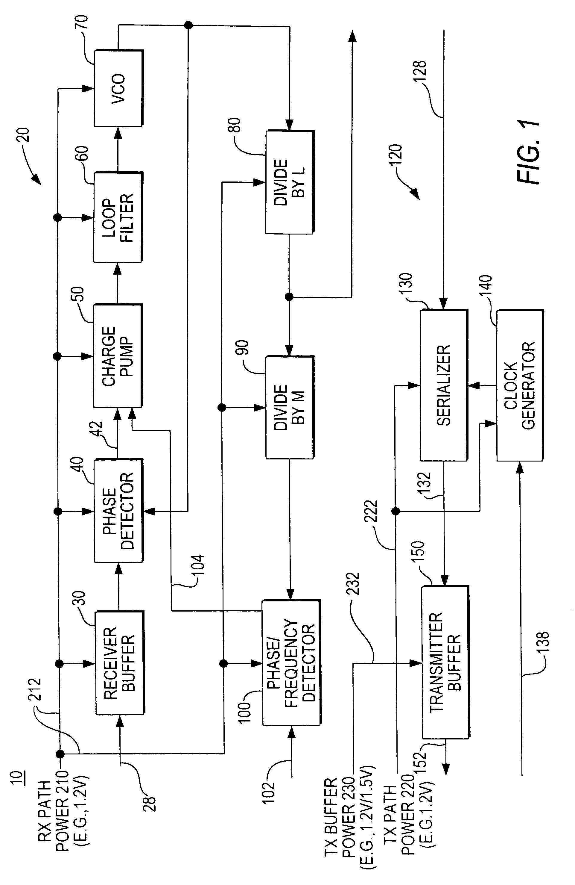
[0012]Illustrative transceiver circuitry 10 for one channel of high-speed serial data communication is shown (in pertinent part) in FIG. 1. Additional background information about certain aspects of circuitry of this general kind can be found in references such as Aung et al. U.S. patent application Ser. No. 09 / 805,843, filed Mar. 13, 2001, Lee et al. U.S. Pat. No. 6,650,140, Venkata et al. U.S. Pat. No. 6,750,675, Venkata et al. U.S. Pat. No. 6,854,044, Lui et al. U.S. Pat. No. 6,724,328, Venkata et al. U.S. patent application Ser. No. 10 / 317,264, filed Dec. 10, 2002, Venkata et al. U.S. patent application Ser. No. 10 / 637,982, filed Aug. 8, 2003, Lam et al. U.S. patent application Ser. No. 10 / 621,074, filed Jul. 15, 2003, Venkata et al. U.S. patent application Ser. No. 10 / 670,813, filed Sep. 24, 2003, Shumarayev U.S. patent application Ser. No. 11 / 211,989, filed Aug. 24, 2005, and Shumarayev et al. U.S. patent application Ser. No. 11 / 230,002, filed Sep. 19, 2005.

[0013]Transceiver c...


PUM


Abstract

The various components of transceiver circuitry on an integrated circuit are put together in various ways for purposes of being supplied with power to help prevent noise propagation between the groups. In the case of multi-channel transceiver circuitry there can be various amounts of power supply sharing between similar groups in multiple channels.

Description

[0001]This application claims the benefit of U.S. provisional patent application No. 60 / 712,027, filed Aug. 26, 2005, which is hereby incorporated by reference herein in its entirety.BACKGROUND OF THE INVENTION[0002]There is increasing interest in using high-speed serial data signaling for communication among devices such as integrated circuits. Some protocols for such communication require the use of several serial channels in parallel. Each channel may include several components that are very sensitive to noise in their power supply signals. One possible way to address this problem is to provide a separate power supply for each such noise-sensitive component. However, this can lead to a requirement for unacceptably large numbers of separate power supplies, especially for devices having large numbers of channels for high-speed serial communication.[0003]An additional problem that may arise in integrating high-speed serial transceivers into programmable logic devices (“PLDs”) and si...

Claims


Application Information

Patent Timeline
IPC IPC(8): H04B1/04
CPCH04L7/033
Inventor SHUMARAYEV, SERGEY YURYEVICHPATEL, RAKESHBEREZA, WILLIAMWONG, WILSONHOANG, TIM TRI
Owner ALTERA CORP
Why Eureka
Try Eureka