Wind turbine rotor with venturi tube effect

a wind turbine and rotor technology, applied in the field of rotor systems, can solve the problems of low average wind energy utilization coefficient, high aerodynamic noise of blade cutting airstream, and many problems to be solved, so as to achieve the effect of high wind energy utilization efficiency, simple and efficient, and improved wind energy utilization efficiency

Inactive Publication Date: 2011-07-21
SHANGHAI FOREVOO NEW ENERGY SYST +1
View PDF13 Cites 10 Cited by
  • Summary
  • Abstract
  • Description
  • Claims
  • Application Information

AI Technical Summary

Benefits of technology

[0006]A purpose of the present invention is to provide a rotor system that is both simple and efficient and can particularly utilize the Venturi-tube effect, so as to overcome technical drawbacks and disadvantages of the existing technology. This rotor system can improve the wind energy utilization efficiency, and can particularly acquire the wind energy utilization efficiency as high as possible in a specific swept area; it can make the WECS more compact in size; it can make the WECS operated more safely; and it can reduce noise pollution of the WECS.
[0008]The present invention is advantageous in the following aspects: The air-intaking amount and the air-intaking speed are increased due to utilization of the Venturi-tube effect, and particularly due to the design of a special WECS rotor based on the Venturi-tube effect principle. Thus the aerodynamic lift for the rotor will be increased according to the Bernoulli principle. Hence the turning torque will be increased, with which the useful work is also increased. More importantly, this WECS rotor can therefore lower the requirement for the start-up wind speed, allowing easy electricity generation at a low start-up wind speed. Therefore, this WECS rotor facilitates great expansion of speed and zone range where the WECS can be developed and applied as well as wide application of the WECS. Moreover, the linear speed of this rotor at the cut-in wind position is greatly reduced compared with that of the three-bladed horizontal-axis-rotor WECS, and thus the airstream friction noise is greatly reduced, hence preventing the noise pollution. Since the high linear speed is prevented and reduced, the harm to birds is also greatly reduced. Because the blade is mounted by means of the twin head connection and the linear speed reduced as well, the harm done by the centrifugal force is also significantly reduced, thus improving safety.

Problems solved by technology

For those skilled in the WECS technical field, there are always many problems to be solved.
However, it still has some drawbacks, such as it has a lower average wind energy utilization coefficient.
Moreover, a drawback of the three-bladed horizontal-axis-rotor WECS is that the tip-speed ratio of the horizontal-axis-rotor turbine is generally about 4-7; under such high speed conditions, the blade cutting airstream will produce a very high aerodynamic noise, and meanwhile a lot of birds can hardly survive.
Therefore, some countries begin to limit and even forbid practical application of this kind of WECS.
Furthermore, with a very high turbine turning speed of the running horizontal-axis-rotor WECS, a large centrifugal force under very strong wind conditions will usually result in breakup and damage of the rotor, even a “runaway” injury accident.
That is, the horizontal-axis-rotor WECS is not safe enough.
Besides, it is not suitable to be mounted at such places as roofs and high buildings in a city, which also limits its application location.
However, all the various disclosed technical approaches can hardly solve the above problems ideally, either for the horizontal-axis-rotor WECS or for the vertical-axis-rotor WECS.

Method used


Image

  • Wind turbine rotor with venturi tube effect
  • Wind turbine rotor with venturi tube effect
  • Wind turbine rotor with venturi tube effect

Examples


Embodiment Construction

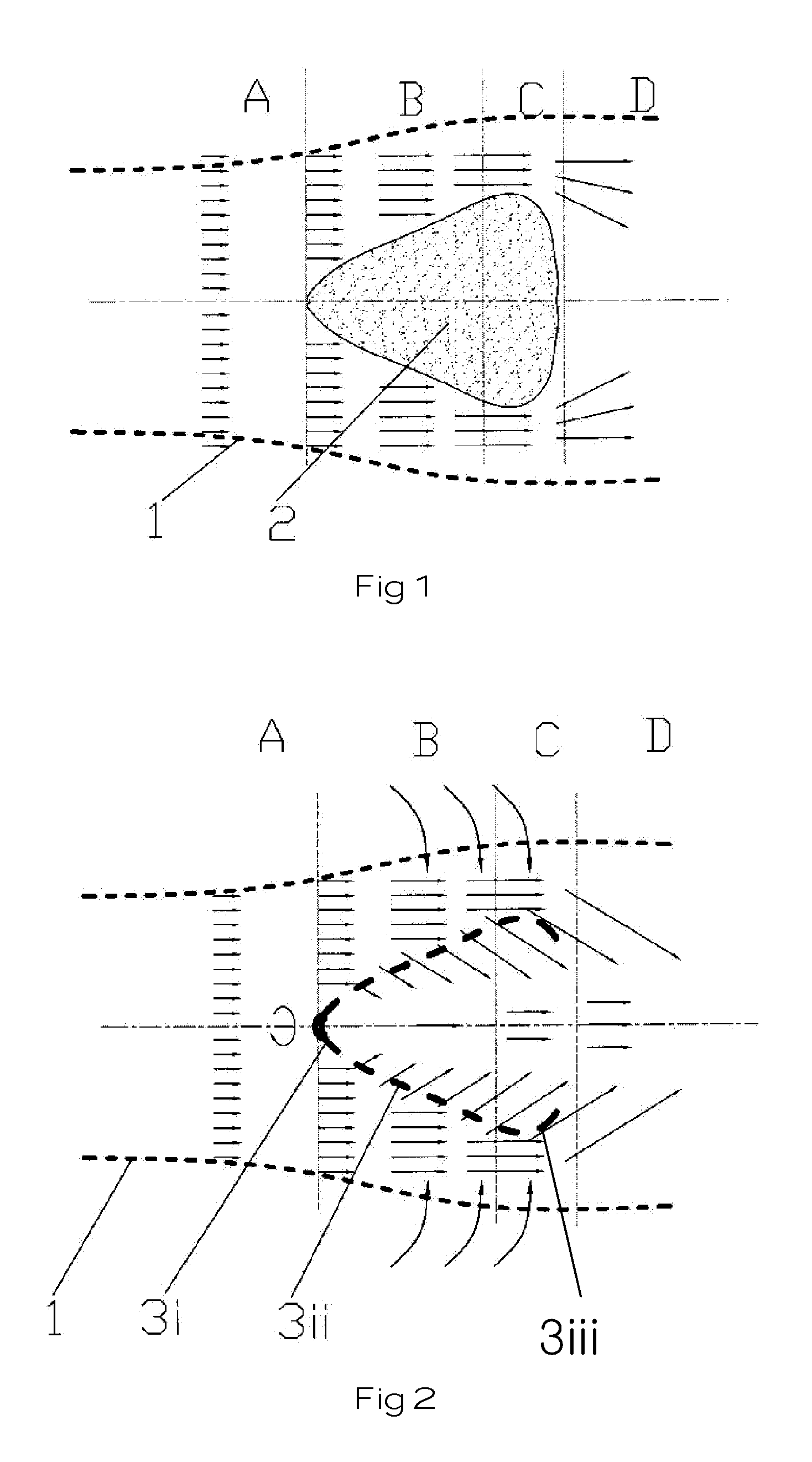
[0027]The following information can be known according to the common aerodynamics principles about the “Bernoulli principle” and particularly the “Venturi-tube effect”: A fluid increased in the flow speed will result in the fluid reduced in the pressure; the Venturi-effect tube is based on the Bernoulli principle, that is, the higher the flow speed of the fluid is, the lower the pressure is; the Venturi-effect tube principle is that the air pressure around the upper edge of the lee of an obstacle is relatively lower when the wind blows the obstacle, thus producing an adsorption effect and causing the airflow. The Venturi-effect tube principle is described as below: Constituting a compressed flow field for making the airstream “change from thick to thin”, so as to speed up the airstream; the accelerated flow speed will surely result in the reduced fluid pressure, making a “vacuum” area formed at the rear of the outlet of the Venturi-effect tube; this vacuum area will attract the surr...


PUM


Abstract

The present invention discloses a rotor of wind energy conversion system (WECS) with the Venturi-tube effect. All the blades mounted on the blade-mounting seat envelop together to form a revolving-body cage turbine, which can be divided from structure into a head portion at the windward end, a tail portion at the wind exhaust end, and an airstream compression portion between the head portion and the tail portion and constituted by the enveloping blades. The revolution diameter of the airstream compression portion is gradually substantially increased from the head portion to the tail portion. The cage turbine forms a dynamic Venturi tube during the revolving process, with which the blade revolves to constitute its outline tube wall with the air permeability. The airstream passes through a window between the blades, and the incoming wind does work towards the blade during the process of permeating from the external space to the internal space of this outline tube wall, thus realizing the energy transfer.

Description

FIELD OF THE INVENTION[0001]The present invention relates to a rotor system of the wind energy conversion system (WECS), and particularly to a WECS rotor with the Venturi-tube effect.BACKGROUND OF THE INVENTION[0002]For those skilled in the WECS technical field, there are always many problems to be solved. For example, how to improve the wind energy utilization efficiency, and particularly how to acquire the wind energy utilization efficiency as high as possible in a specific swept area; how to make the WECS more compact in size; how to operate the WECS more safely; and how to reduce noise pollution of the WECS.[0003]The existing well-known common three-bladed horizontal-axis-rotor WECS is the most universal and representative WECS. However, it still has some drawbacks, such as it has a lower average wind energy utilization coefficient. Although the highest value is 0.593 according to the Betts Limit theory, this value can never be reached. The most advanced current technical index ...

Claims


Application Information

Patent Timeline
Patent Type & Authority Applications(United States)
IPC IPC(8): F04D29/38
CPCF03D1/0608F05B2240/301Y02E10/721F05B2250/25F05B2250/232Y02E10/72
Inventor ZHANG, YUNLONG
Owner SHANGHAI FOREVOO NEW ENERGY SYST
Why Eureka
Try Eureka