
Method for forming pile in stratum with hard rock stratum in lower part

A rock formation and hard technology, applied in the field of underground engineering, can solve the problems of low efficiency of single pile hole formation, hole bottom damage, poor pile quality, etc., to meet the requirements of safe and civilized and green construction, avoid environmental hazards, and save energy. The effect of the construction period

Active Publication Date: 2017-03-29
CCCC SECOND HARBOR ENG +2
View PDF5 Cites 9 Cited by
  • Summary
  • Abstract
  • Description
  • Claims
  • Application Information

AI Technical Summary

Problems solved by technology

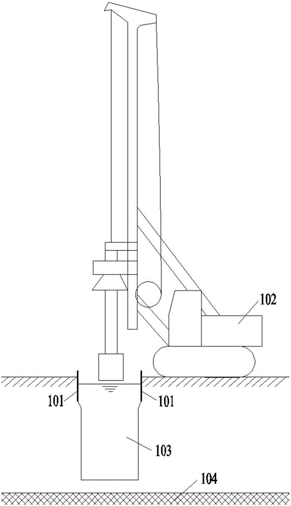
[0004] For strata with hard rock formations at the bottom ("upper soft and lower hard" strata), the conventional rotary excavation pile-forming process is used for pile construction. After entering the hard rock stratum, the drilling speed is slow and affects the construction progress; the usual countermeasure is to use The percussion drill and the rotary drill are combined for pile-forming construction, but the rock formation is relatively hard, such as slightly weathered rock formation, the drilling efficiency of the percussion drill is also slow, and it is easy to cause damage to the bottom of the hole, not only the quality of the pile cannot be guaranteed , the vibration and noise generated during the construction process will also have adverse effects on the surrounding environment; the use of blasting method to construct piles in hard rock formations also faces problems such as poor pile quality, vibration and noise pollution, and is limited by the surrounding environmental conditions
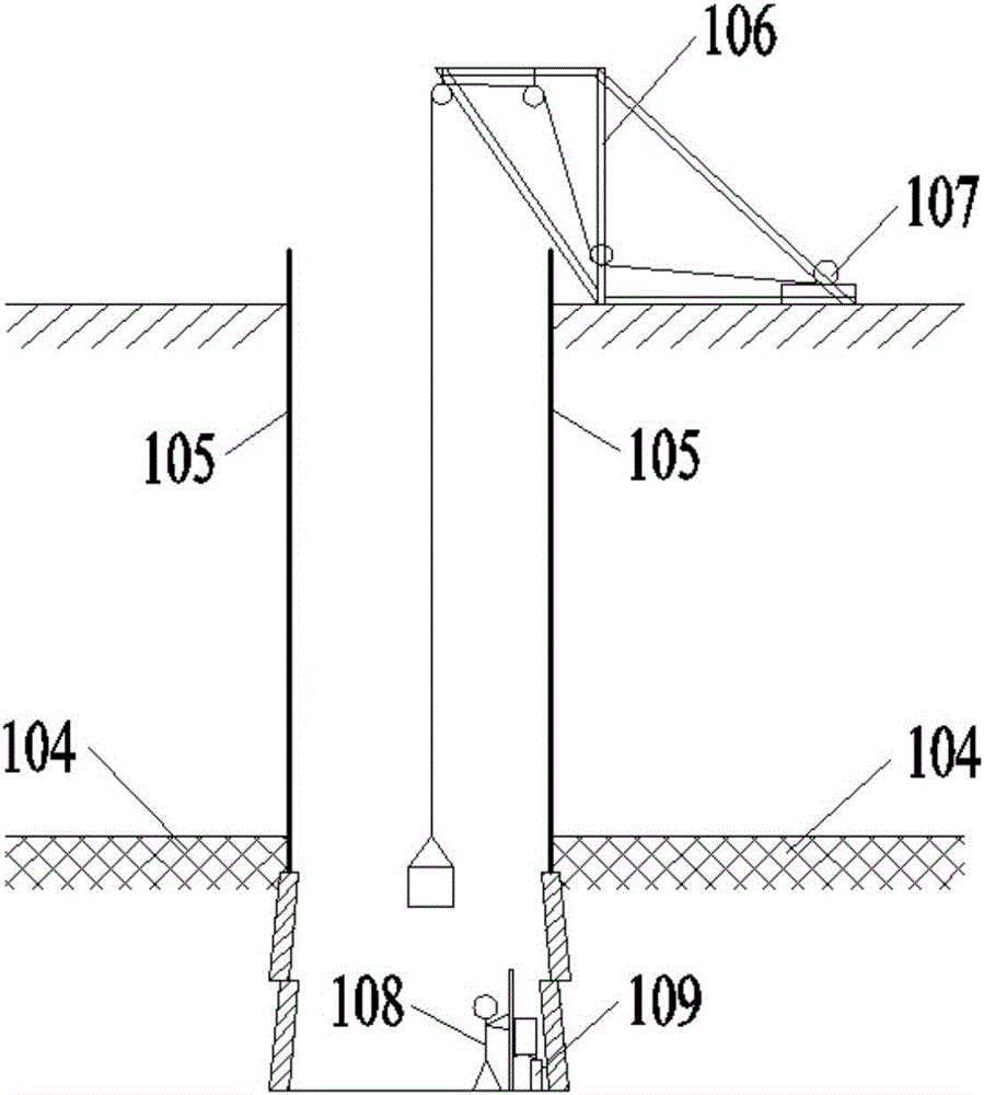
However, under this stratum condition, if all manual hole-digging piles are used for construction, the hole-forming efficiency of the single pile is too low, and manual underground operations are used for a long time in a large area, and personal safety hazards are also extremely serious.

Method used


Image

  • Method for forming pile in stratum with hard rock stratum in lower part
  • Method for forming pile in stratum with hard rock stratum in lower part

Examples


Embodiment Construction

[0029] The present invention will be further described in detail below in conjunction with the accompanying drawings, so that those skilled in the art can implement it with reference to the description.

[0030] It should be noted that the experimental methods described in the following embodiments, unless otherwise specified, are conventional methods, and the reagents and materials, if not otherwise specified, can be obtained from commercial sources; in the description of the present invention, The terms "landscape", "portrait", "top", "bottom", "front", "rear", "left", "right", "vertical", "horizontal", "top", "bottom", The orientation or positional relationship indicated by "inner", "outer", etc. is based on the orientation or positional relationship shown in the drawings, which is only for the convenience of describing the present invention and simplifying the description, and does not indicate or imply that the referred device or element must have Certain orientations, co...


PUM


Abstract

The invention discloses a method for forming a pile in a stratum with a hard rock stratum in a lower part. The method comprises the following steps: drilling by adopting a rotary drilling rig, and stopping drilling construction when the rotary drilling rig reaches the hard rock stratum; continuing drilling to a designed elevation by adopting a water mill drilling rig; cleaning the bottom of a hole, placing a steel reinforcement cage into the drilled hole, and then filling pile body concrete. According to the method, vibration and noise pollution caused by hard rock impact and blasting are avoided; a secondary hole cleaning link after the hole is finished is also omitted; the problems of hole bottom sludge and difficulty in loosen soil cleaning are solved; respective advantages of the rotary drilling rig and a manual hole digging pile are fully played; the construction period can be effectively shortened; the construction cost can be reduced; the construction quality can be ensured; the method is not limited by ambient environment; the requirements of safe, civilized and green construction are met.

Description

technical field [0001] The invention relates to the technical field of underground engineering. More particularly, the present invention relates to a method of piling in an underlying formation of hard rock. Background technique [0002] The drilling principle of the rotary drilling rig is to cut into the soil layer with the help of the self-weight of the drilling tool and the pressure of the drilling rig. The inclined bucket teeth cut off the soil block and push it into the bucket to complete the soil retrieval when the bucket rotates. It is suitable for dry and wet drilling. For operation, the conventional wet rotary drilling adopts the soil extraction process of the static mud wall protection drill bucket. It is widely used in pile foundation projects such as highway bridges, railways, municipal and water conservancy projects because of its advantages such as fast hole forming speed, flexible movement, high degree of automation, environmental protection and wide applicat...

Claims


Application Information

Patent Timeline
Patent Type & Authority Applications(China)
IPC IPC(8): E02D5/34E02D5/38
CPCE02D5/34E02D5/38
Inventor 杨钊熊栋栋刘毅杨擎陈培帅余村冯德定许超孔茜
Owner CCCC SECOND HARBOR ENG
Learn More