Wind tunnel

a wind tunnel and air technology, applied in the field of aerodynamics, can solve the problems of increasing the air pressure loss in the diffuser, affecting the performance of the wind tunnel, so as to reduce the power and reduce the consumption of materials

Inactive Publication Date: 2010-01-05
PETRUK VICTOR
View PDF10 Cites 1 Cited by
  • Summary
  • Abstract
  • Description
  • Claims
  • Application Information

AI Technical Summary

Benefits of technology

[0006]The purpose of the present invention is to construct a return-flow wind tunnel with low air pressure loss that results in reduced power for driving the wind tunnel blower unit and reduced materials consumption (a specific amount of metal per structure) in constructing the wind tunnel.
[0009]As air pressure loss is directly proportional to the squared local velocity, the total airflow loss corresponding to the defined pressure recovery factor in the diffuser section between the first turning bend and the second turning bend would decrease because the main part of the total airflow loss coefficient for the turning bands corresponds to the section of the wind tunnel circuit with lesser flow velocity. Additionally, the reduction of the airflow loss coefficient for the first turning bend provides a possibility to increase the airflow velocity in the area of this turning bend and, as a result, to reduce the area ratio and the length of the diffuser in order to reduce the air pressure loss in the diffuser, the overall dimensions of the diffuser, and the materials consumption in constructing the wind tunnel.

Problems solved by technology

The disadvantage of the prior art wind tunnel is a significant air pressure loss due to an inefficient arrangement of the wind tunnel elements.
The first turning bend and the second turning bend are main sources of the air pressure loss in the wind tunnel circuit and induce a large air pressure loss in the diffuser.
As a result, the air pressure loss in the diffuser would increase.
Additionally, the increase of the area ratio of the diffuser is associated with the increase of the length of the diffuser and, as a result, with the increase of the overall dimensions of the wind tunnel and the increase of materials consumption in constructing the wind tunnel.

Method used


Image

  • Wind tunnel
  • Wind tunnel

Examples


Embodiment Construction

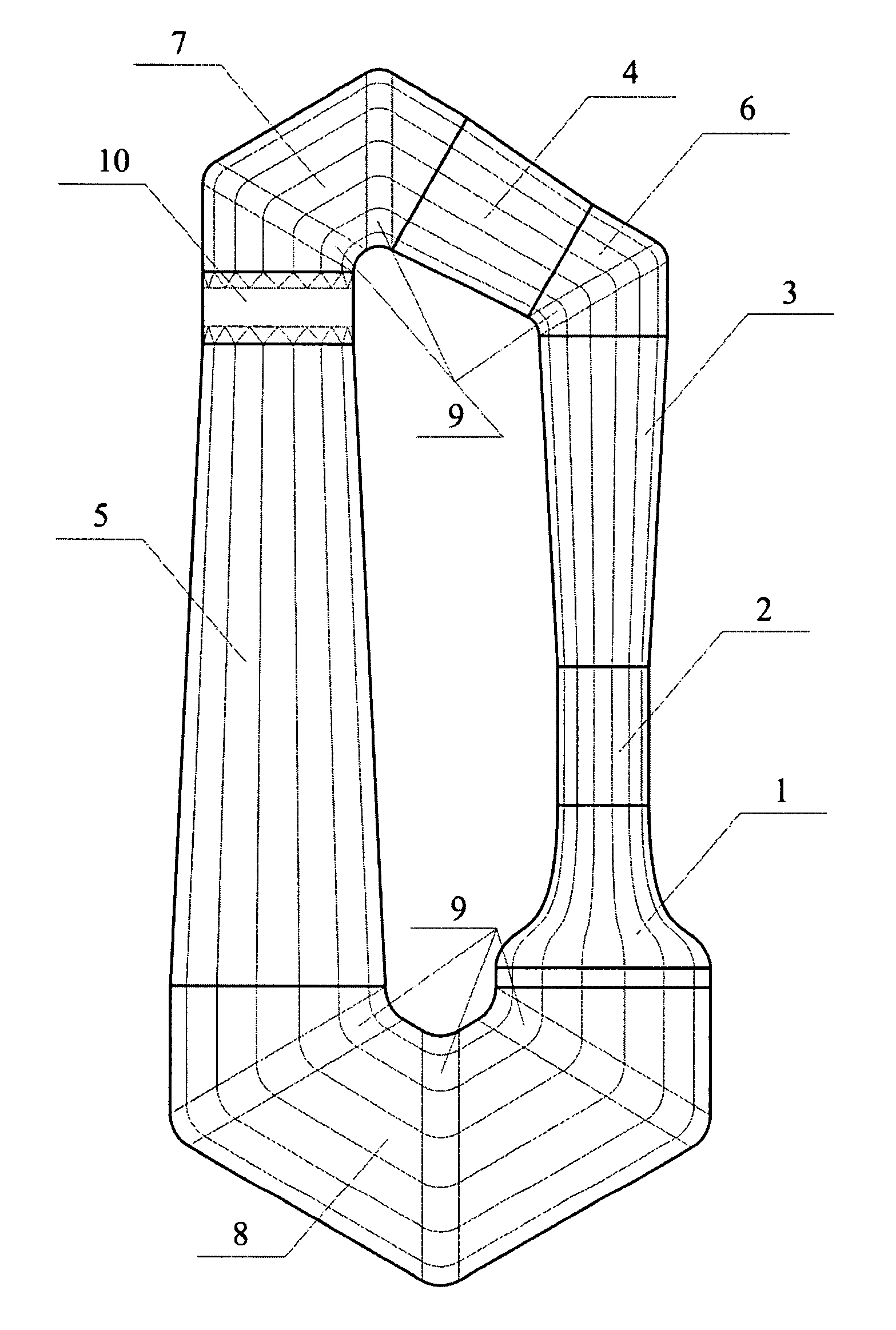
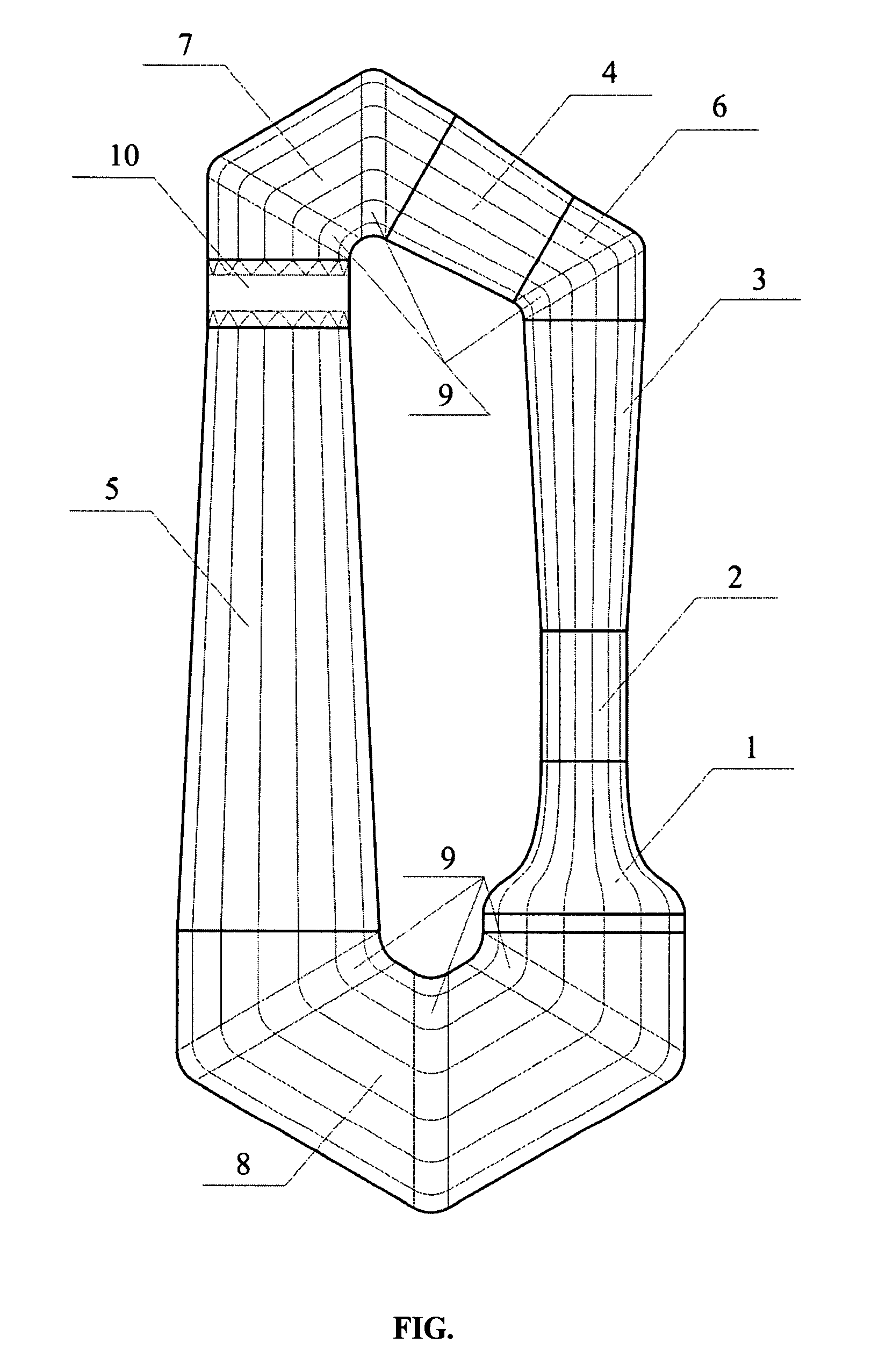
[0010]While the invention may be susceptible to embodiment in different forms, there is shown in an appended drawing FIGURE (FIG.), and will be described in detail herein, a specific embodiment of the present invention, with the understanding that the present disclosure is to be considered an exemplification of the principles of the invention, and is not intended to limit the invention to that as illustrated and described herein.

[0011]For the purpose to reduce the airflow loss coefficient for the turning bends with a flow turning angle more than 90 degrees, the turning bend may contain several turning guts. Specifically, the wind tunnel may contain turning bends with turning guts, each of which can turn the airflow at an angle of 60 degrees. The first turning bend contains one turning gut for turning the airflow at 60 degrees, the second turning bend contains two turning guts for turning the airflow at 120 degrees, and the third turning bend contains three turning guts for turning t...


PUM


Abstract

The invention relates to closed-circuit tunnels used for aerodynamic researches, sportsmen-parachutists training and other purposes. The inventive closed-circuit tunnel comprises a confuser, a working area, a diffuser, one or several return channels, a blower unit and turning bends having different flow deflection angle, wherein the bend having the smaller flow deflection angle is placed in a high-speed flow cross-section, whereas the bend having the greater flow deflection angle is arranged in a low flow speed cross-section. In a preferred embodiment, the tunnel comprises a first turning bend containing one turning gut for turning the airflow at 60 degrees, a second turning bend containing two turning guts for turning the airflow at 120 degrees, and a third turning bend containing three turning guts for turning the airflow at 180 degrees. The invention makes it possible to reduce air pressure losses, the drive power and a specific amount of metal per structure.

Description

CROSS-REFERENCE TO RELATED APPLICATIONS[0001]This application is a U.S. national phase application of a PCT application PCT / UA2006 / 000029 filed on 23 May 2006, published as WO2006 / 130125, whose disclosure is incorporated herein in its entirety by reference, which PCT application claims priority of a Ukrainian patent application UA2005 / 05083 filed on 30 May 2005.FIELD OF THE INVENTION[0002]The present invention relates to aerodynamics and can be used in designing wind tunnels. Particularly, the invention is dedicated to closed-circuit tunnels used for aerodynamic researches, sportsmen-parachutists training and for other purposes.BACKGROUND OF THE INVENTION[0003]Every known return-flow wind tunnel contains a confuser, a test section, a diffuser, a blower unit, one or several return channels, and turning bends that are used to form a closed loop. The turning bend may be designed as a smooth arc-shaped section for turning airflow through 180 degrees [1, p. 64] or as an elbow bend for tu...

Claims


Application Information

Patent Timeline
Patent Type & Authority Patents(United States)
IPC IPC(8): G01M9/00
CPCG01M9/02
Inventor PETRUK, VICTOR
Owner PETRUK VICTOR
Why Eureka
Try Eureka