Multiple tape application method and apparatus

a technology of multi-tape and tabs, applied in the field of multi-tape tabs application methods and apparatuses, can solve the problem of almost unnoticeable cutting noise level, achieve the effect of reducing the level of vacuum, reducing the moment of inertia of the tape segment, and reducing the coefficient of friction between the protuberances and the traveling web

Active Publication Date: 2010-01-05
CURT G JOA
View PDF443 Cites 50 Cited by
  • Summary
  • Abstract
  • Description
  • Claims
  • Application Information

AI Technical Summary

Benefits of technology

[0012]The invention provides the additional benefit of quiet operation compared to prior art equipment, which use high speed cutting faces and suffers from the effects of the very high energy levels seen at the point of contact. Generally, these energies, and the sounds that they generate, increase in proportion to the square of the velocity. The present invention benefits from the relatively low speed of the cutting faces and exhibits extremely low noise levels. In fact, the underlying noise of the mechanical drive systems and the traveling web equipment contribute to make the cutting noise level nearly unnoticeable.
[0017]Given the extremely low moment of inertia of the tape segments and the aggressive adhesion provided between its exposed adhesive and the compatible surface of the traveling web, each successive segment is successfully transferred to the traveling web, accelerating almost instantly to the speed of the traveling web.
[0018]A key aspect of this invention lies in the method and apparatus used to affect the transfer of the tape segments from the anvil to the traveling web. In accordance with the invention, a vacuum commutation system is configured to remove or reduce the level of vacuum used to hold each tape segment to the anvil surface just before the point of transfer. The materials and finishes selected for the anvil and the transfer protuberances provide a situation in which the coefficient of friction between the protuberances and the traveling web is relatively high, while the coefficient of friction between the tape segment and the anvil is relatively low. The highly aggressive nature of the bond between the adhesive side of the tape segment and the target surface of the traveling web ensures that there is virtually no slippage between the two. This ensures that the traveling web is driven through the point of transfer at its existing velocity, and that any tendency of the tape segment to adhere to the anvil surface will not influence the traveling web. The process requires that some slip occurs, and in accordance with the invention, slip occurs only between the tape segment and the anvil surface.

Problems solved by technology

In fact, the underlying noise of the mechanical drive systems and the traveling web equipment contribute to make the cutting noise level nearly unnoticeable.

Method used


Image

  • Multiple tape application method and apparatus
  • Multiple tape application method and apparatus
  • Multiple tape application method and apparatus

Examples


Embodiment Construction

[0023]Although the disclosure hereof is detailed and exact to enable those skilled in the art to practice the invention, the physical embodiments herein disclosed merely exemplify the invention which may be embodied in other specific structure. While the preferred embodiment has been described, the details may be changed without departing from the invention, which is defined by the claims.

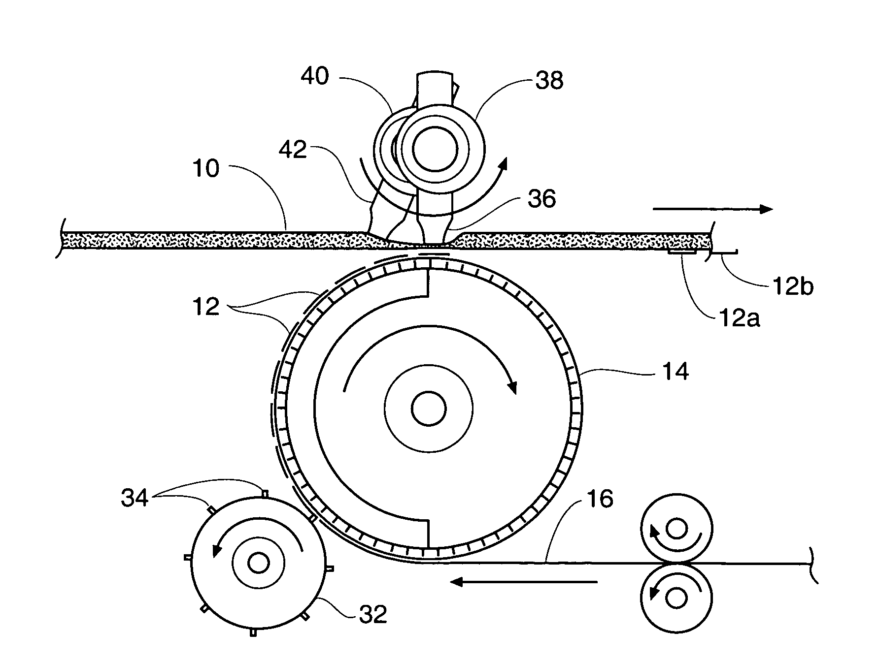
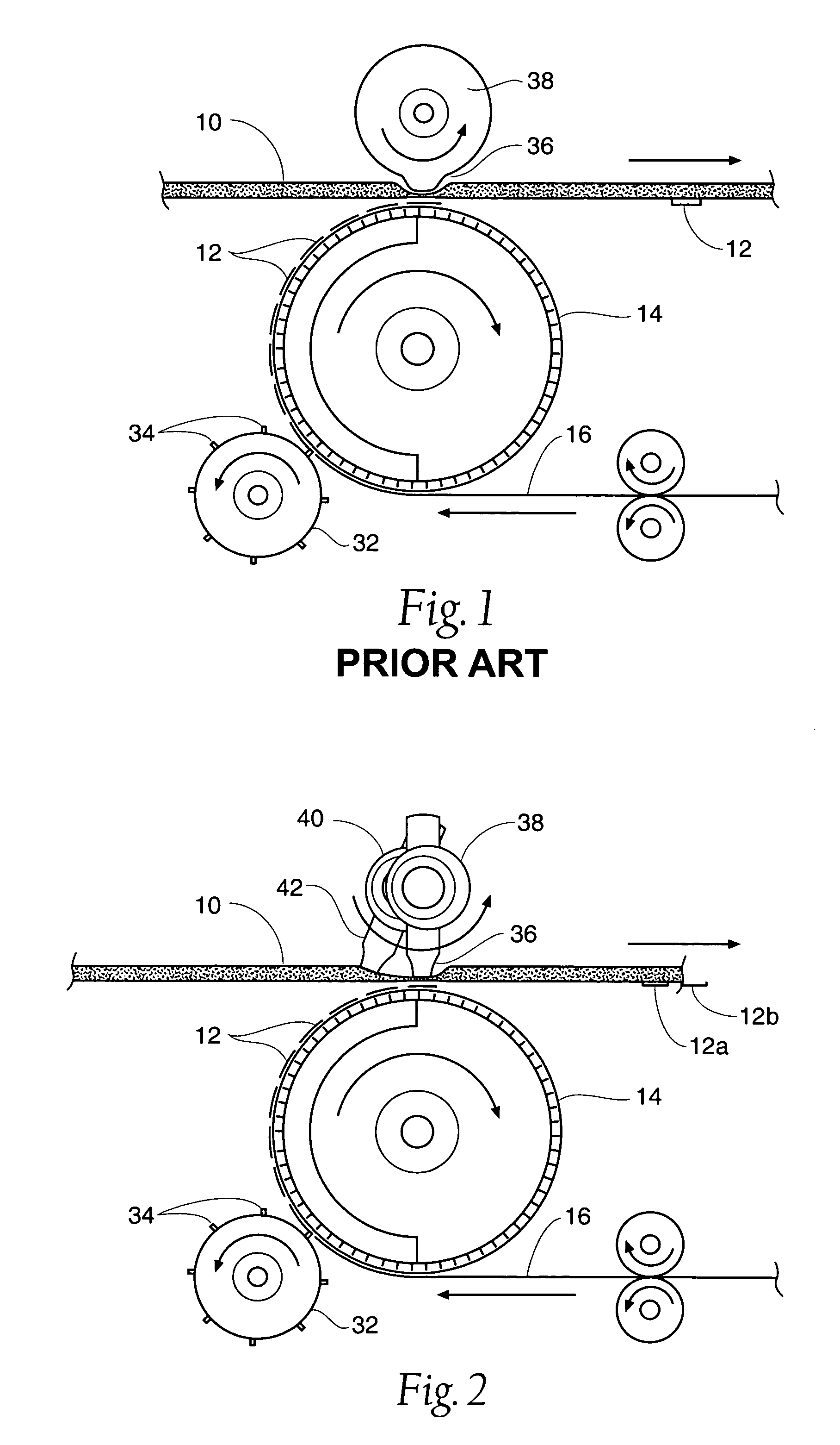
[0024]Referring to FIG. 1, the apparatus and process of the Prior Art is shown in diagrammatic fashion. In accordance with the invention, the web 16 is fed to the anvil 14 at a speed such that the web speed of web 16 approximately equals the speed at which the outer periphery of anvil 14 is traveling. If desired, the anvil 14 may rotate at a slightly higher speed than the linear speed of the web 16. The blades 34 of a rotary cutter 32 are also traveling at a peripheral speed equal to that of anvil 14. After cutting the web 16, a series of tabs 12 are carried on the outer surface of anvil 14. Tabs 1...


PUM

PropertyMeasurementUnit
lengthaaaaaaaaaa
lengthaaaaaaaaaa
adhesiveaaaaaaaaaa

Abstract

A method and apparatus for applying tape tabs to a traveling web of material, for example, placement of tape tabs on a running web of disposable undergarments. A pair of wheels each has a protuberance come in contact with the running web of material, which comes in contact with an infeeding tape web. The invention allows placement of tape tabs at asymmetrical spacings, where placement of the tape from contact of the first wheel and protuberance may not be equally or centrally spaced from placement of the tape by the second wheel and protuberance.

Description

RELATED APPLICATION[0001]This application claims the benefit of U.S. Provisional Patent Application Ser. No. 60 / 563,634, filed 20 Apr. 2004, and entitled “Multiple Tape Application Method and Apparatus.”BACKGROUND OF THE INVENTION[0002]The present invention relates to processes and apparatus for applying tabs to traveling webs, and more specifically to application of multiple tabs to a traveling web. The invention has particular applicability to the manufacture of disposable diapers.[0003]The history of cutting and applying tape tabs to disposable diaper webs is now in its fourth decade. Over the course of that time, various types of automatic manufacturing equipment have been developed which produce the desired results with a variety of materials and configurations. This equipment generally included window-knife and slip-and-cut applicators, each having their own advantages and limitations.[0004]Window-knife applicators are comprised of: one or more rotating heads, each made up of ...

Claims


Application Information

Patent Timeline
Patent Type & Authority Patents(United States)
IPC IPC(8): B29C65/50B29C65/56B29C65/80B32B37/22B65C9/30B44C1/24B32B37/26B65C9/20B44C1/17B65H19/00B65H39/14
CPCB65H39/14B65H2301/121B65H2801/57Y10T156/133Y10T156/1322Y10T156/1084Y10T156/1052Y10T156/1339Y10T156/1744
Inventor MEYER, THOMAS C.PARRISH, TIMFRITZ, JEFF W.
Owner CURT G JOA
Why Eureka
Try Eureka