Explosion proof lantern

a portable, lantern technology, applied in the direction of lighting and heating equipment, instruments, process and machine control, etc., can solve the problems of simultaneous failure of electric equipment, inability to safely use conventional lanterns, and inability to use conventional lanterns, etc., to achieve convenient use, cost-effective, durable and convenient

Inactive Publication Date: 2010-01-05
SUNLITE SAFETY PRODS
View PDF14 Cites 49 Cited by
  • Summary
  • Abstract
  • Description
  • Claims
  • Application Information

AI Technical Summary

Benefits of technology

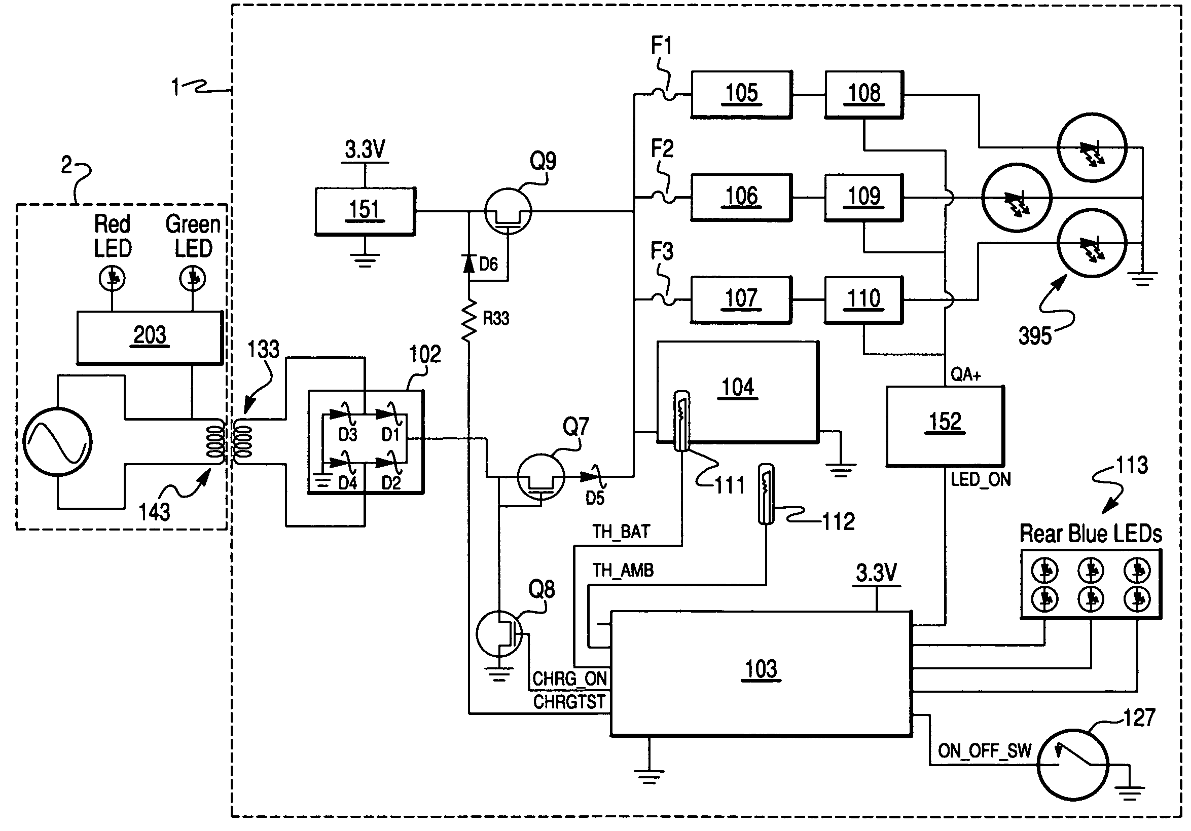
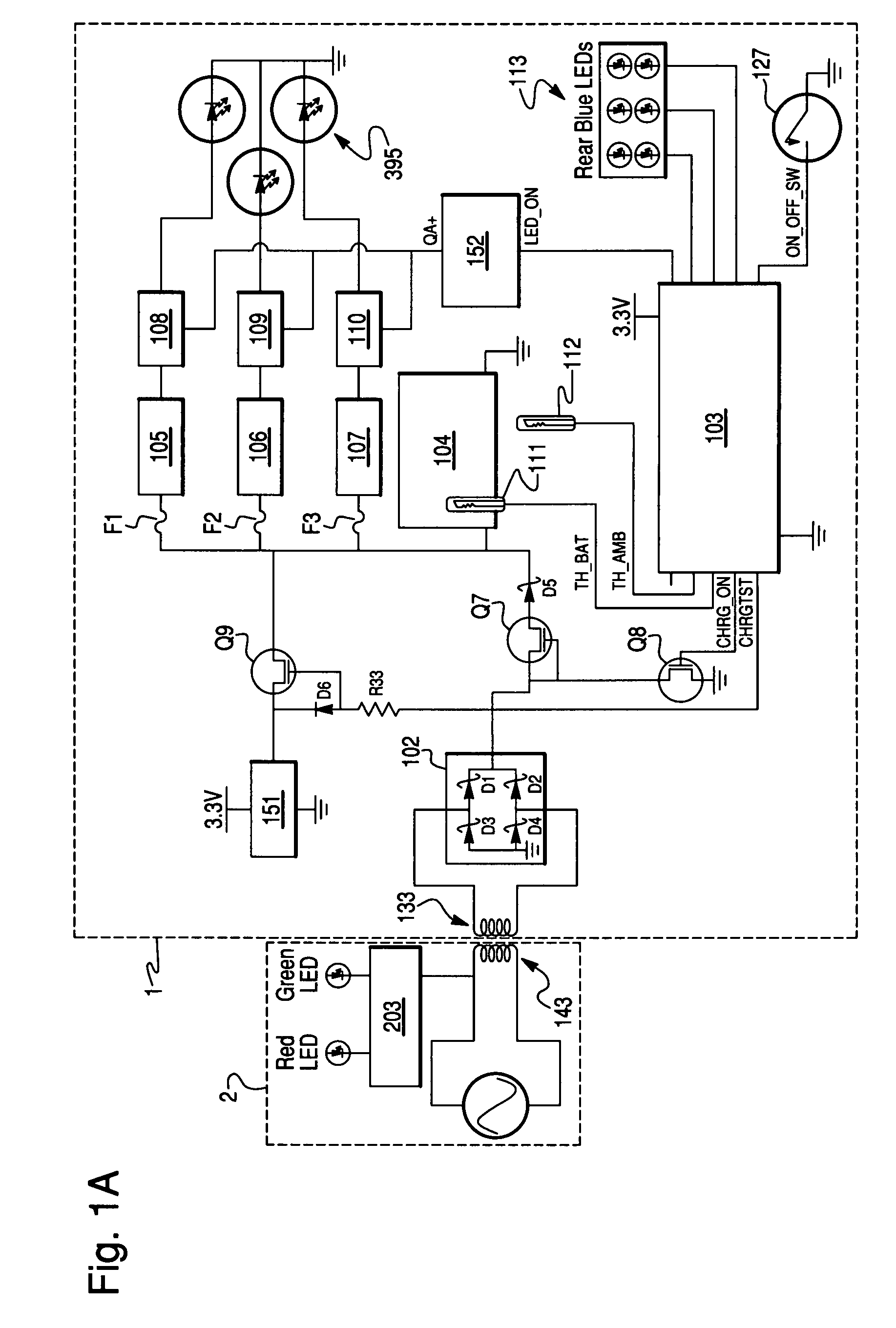
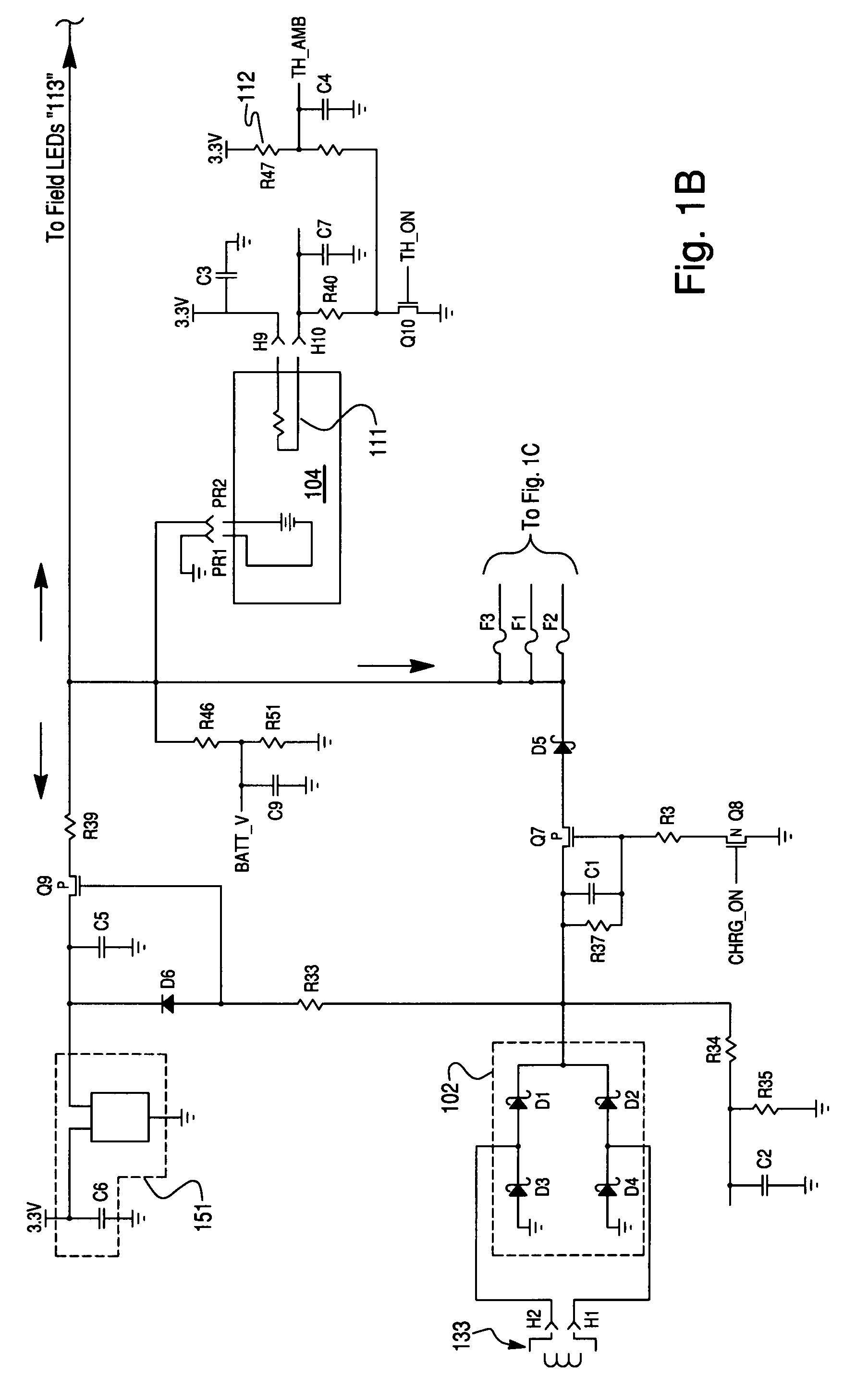
[0005]The present invention provides a portable explosion proof lantern with fault proof electronic circuitry that can be used in all explosive environments that may be encountered, not just limited to certain explosive environments. Various embodiments of the present invention provide inductively rechargeable batteries for powering the device, obviating the need for disposable batteries. Further embodiments include a portable lantern with a pivoting rotating head with a multiple LED light packaged within an unbreakable explosion proof lantern body. Other embodiments provide a portable easy to use lantern for the hazardous environments that does not require an external power supply or require extension cords for the power that is more cost effective, durable and easier to use.

Problems solved by technology

However, in a wide variety of hazardous environments conventional lanterns are unusable.
A Class I, Division I work environment is a location in which: (a) hazardous concentrations of flammable gases or vapors may exist under normal operating conditions; or (b) hazardous concentrations of such gases or vapors may exist frequently because of repair or maintenance operations or because of leakage; or (c) breakdown or faulty operation of equipment or processes might release hazardous concentrations of flammable gases or vapors, and might also cause simultaneous failure of electric equipment.
Given the high volatility present in these types of working environments, conventional lanterns cannot be safely used since their electrical connections to batteries, hot filaments, exposed metal connections and unsealed switches could cause sparks.

Method used


Image

  • Explosion proof lantern
  • Explosion proof lantern
  • Explosion proof lantern

Examples


Embodiment Construction

[0020]The various embodiments will be described in detail with reference to the accompanying drawings. Wherever possible, the same reference numbers will be used throughout the drawings to refer to the same or like parts.

[0021]As used herein, the terms “about” or “approximately” for any numerical values or ranges indicates a suitable dimensional tolerance that allows the part or collection of components to function for its intended purpose as described herein. As used herein, the terms “high voltage,”“high signal,”“low voltage” and “low signal” refer to voltage levels corresponding to “1” or “0” in a digital logic circuit, such as a microcontroller.

[0022]OSHA has mandated that the only lantern than can be used in Class 1 Division 1 environments is a Class 1 Division 1 rated intrinsically safe light. Currently, there is no portable rechargeable lantern available in the world with this rating. The only lanterns available today for use in Class 1, Division 1 environments are lights wit...


PUM


Abstract

A portable rechargeable lantern capable of use in an explosive environment includes light emitting diode light source, fault tolerant circuitry, a rechargeable battery and a charging circuit that receives power from an external charger via an induction coil. Formed within a sealed housing, the induction coil charging system eliminates external metal contacts, thereby eliminating a potential ignition source during charging operations. Fault tolerant circuitry and a cool-running light emitting diode light source eliminate potential ignition sources due to breakage or fault conditions. Mating surfaces between the lantern and its charger cradle facilitate aligning the charging induction coils.

Description

FIELD OF THE INVENTION[0001]The present invention generally relates to explosion proof lighting equipment, and more particularly to a rechargeable portable lantern suitable for use in all explosive environments.BACKGROUND OF THE INVENTION[0002]Several occupations require the use of a portable lantern. However, in a wide variety of hazardous environments conventional lanterns are unusable. The Occupational Safety and Health Administration (OSHA) has classified a number of hazardous work environments where special precaution must be taken to provide workers with safe working conditions. The most extreme work environment is classified as Class I, Division 1. A Class I, Division I work environment is a location in which: (a) hazardous concentrations of flammable gases or vapors may exist under normal operating conditions; or (b) hazardous concentrations of such gases or vapors may exist frequently because of repair or maintenance operations or because of leakage; or (c) breakdown or fau...

Claims


Application Information

Patent Timeline
Patent Type & Authority Patents(United States)
IPC IPC(8): F21L4/00
CPCF21L4/08F21V23/00F21V25/12H05B33/0803H05B33/0818F21L2/00H05B33/0815F21Y2115/10F21V29/77Y10S362/80H05B45/345H05B45/30
Inventor SMITH, MIKEGOODMAN, RANDYKELLY, KEVINBRUNDAGE, MARTYKLINE, BRET
Owner SUNLITE SAFETY PRODS
Why Eureka
Try Eureka