Device for controlling clearance in a gas turbine

a technology for controlling clearance and gas turbines, applied in the direction of machines/engines, stators, liquid fuel engines, etc., can solve problems such as insufficient solutions, and achieve the effect of reducing drawbacks

Active Publication Date: 2010-01-05
SN DETUDE & DE CONSTR DE MOTEURS DAVIATION S N E C M A
View PDF6 Cites 18 Cited by
  • Summary
  • Abstract
  • Description
  • Claims
  • Application Information

AI Technical Summary

Benefits of technology

[0007]The turbine casing of the invention thus enables the temperature field of the support ring to be made uniform, so that the support deforms in uniform manner around its entire circumference, without any negative influence on the clearance at the tips of the blades.
[0013]The casing of the invention thus makes it possible both to improve the performance of the engine and to increase the lifetime of the ring support, because the temperature gradients are smaller and the mechanical stresses are thus reduced.
[0014]In addition, the invention can be implemented at very low cost.

Problems solved by technology

Nevertheless, that solution is found to be insufficient when the support to which the ring is secured also suffers thermal deformation around its circumference and in a manner that is not uniform, where such deformation has the effect of deforming the turbine ring.

Method used


Image

  • Device for controlling clearance in a gas turbine
  • Device for controlling clearance in a gas turbine
  • Device for controlling clearance in a gas turbine

Examples


Embodiment Construction

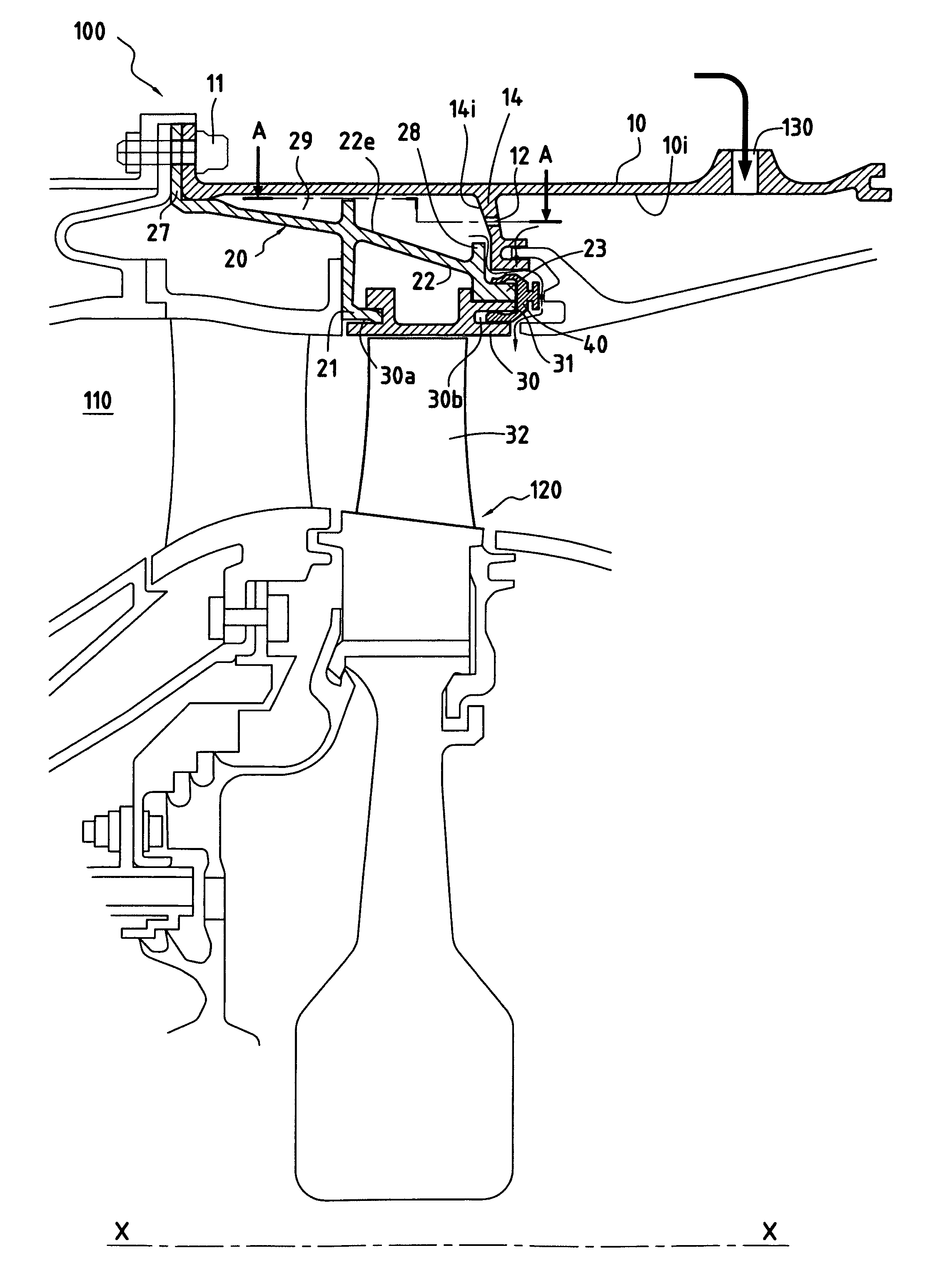
[0020]FIG. 1 is a half-view in longitudinal section showing a turbomachine 100 of the invention in a preferred embodiment.

[0021]In conventional manner, the turbomachine 100 includes a combustion chamber 110.

[0022]Downstream from the combustion chamber 110, the turbomachine 100 includes a turbine 120 in accordance with the invention, and having a casing in accordance with the invention that is given the reference 10.

[0023]In this figure, a stationary ring surrounding the moving blades 32 of the turbine 120 is referenced 30.

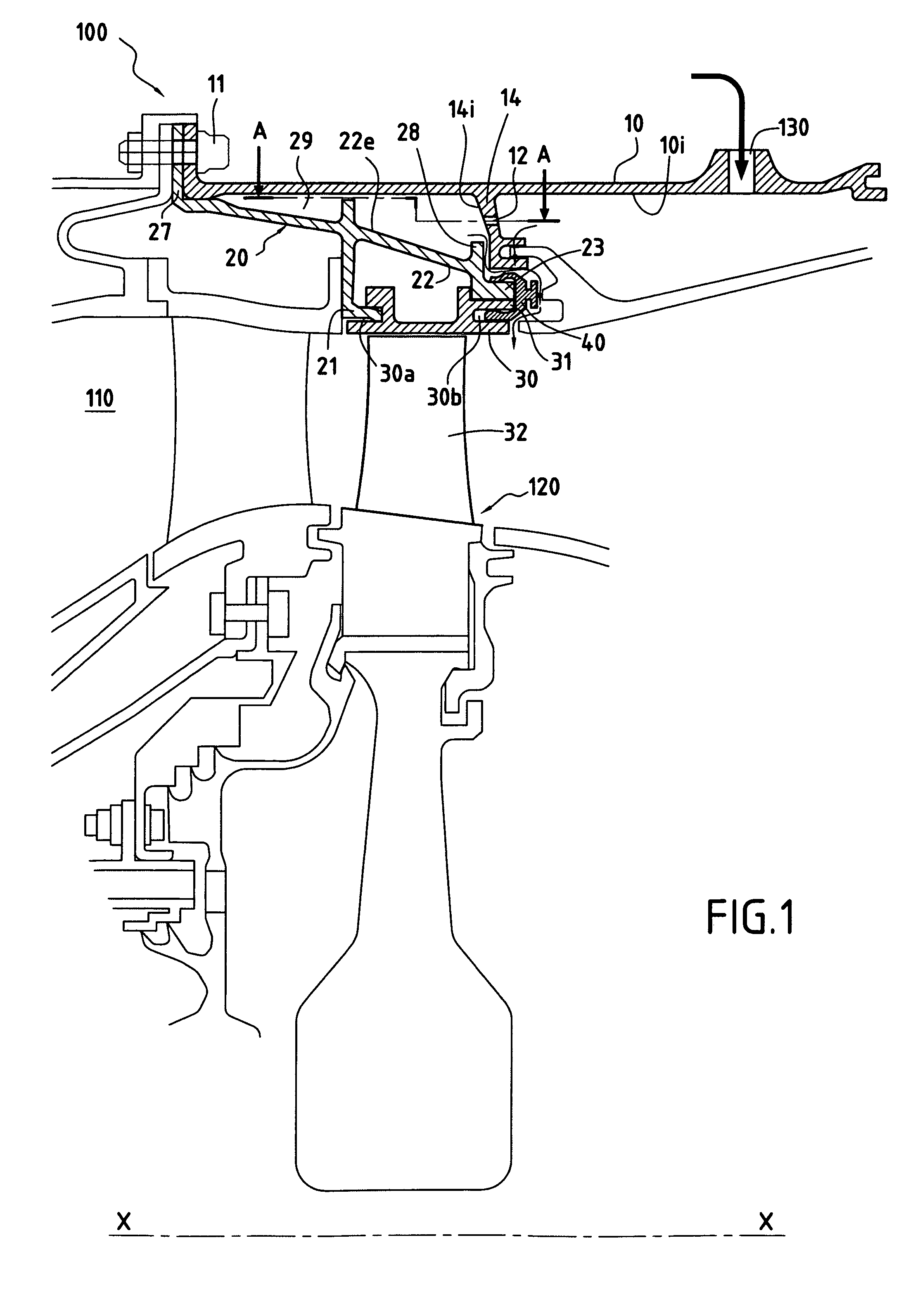
[0024]The ring 30 is secured to an annular support 20. For this purpose, in the embodiment described herein, the ring 30 has a first circular groove 30a in its upstream portion adapted to receive a mounting rail 21 of the support 20.

[0025]In its downstream portion, the ring 30 presents a circumferential flat 31 against which there comes to bear an annular edge 23 of the support 20. Substantially at the same level as the first circular groove 30a, but on its downstr...


PUM


Abstract

The turbine casing includes a circumferential wall coaxially surrounding a ring that surrounds the moving blades of the turbine. The casing includes a plurality of perforations delivering air for ventilating the outside face of the circumferential wall in uniform manner.

Description

BACKGROUND OF THE INVENTION[0001]The present invention relates to the general field of controlling clearance between the tips of rotary blades and a stationary ring assembly in a gas turbine.[0002]A gas turbine, e.g. a high-pressure turbine of a turbomachine, typically comprises a plurality of stationary vanes disposed in alternation with a plurality of moving blades lying on the path of hot gas coming from the combustion chamber of the turbomachine. The moving blades of the turbine are surrounded around the entire circumference thereof by a stationary ring assembly. The stationary ring assembly defines the passage along which the hot gas flows through the blades of the turbine.[0003]In order to increase the efficiency of such a turbine, it is known to reduce the clearance that exists between the tips of the moving blades of the turbine and the facing portions of the stationary ring assembly to a value that is as small as possible.[0004]To achieve this, means have been devised that ...

Claims


Application Information

Patent Timeline
Patent Type & Authority Patents(United States)
IPC IPC(8): F01D11/08
CPCF01D11/24F01D25/12F01D25/24
Inventor DENECE, FRANCK ROGER DENISPHILIPPOT, VINCENT
Owner SN DETUDE & DE CONSTR DE MOTEURS DAVIATION S N E C M A
Why Eureka
Try Eureka