Cleaning an ink chamber of a printing unit

a printing unit and ink chamber technology, applied in printing, office printing, functional valve types, etc., can solve the problems of insufficient cleaning, inability to provide for secure and efficient cleaning of ink chamber, and risk of ink residue giving problems, etc., to achieve convenient replacement of cleaning nozzles, small energy-saving and space-saving high-pressure pumps, and simple

Inactive Publication Date: 2010-01-05
TRESU ANLAEG
View PDF18 Cites 11 Cited by
  • Summary
  • Abstract
  • Description
  • Claims
  • Application Information

AI Technical Summary

Benefits of technology

[0021]The purpose of the present invention is to indicate a system including a method, a system and a cleaning nozzle that enable constructing a technically simple and reliable system working according to a method which enables use of a small energy-saving and space saving high-pressure pump, and which facilitate replacing the cleaning nozzles.

Problems solved by technology

However, the system will not provide for a secure and efficient cleaning of the ink chamber but only flushing, as the pressure at which the cleaning liquid is injected into the pipe depends on the pump capacity in the moment of injection.
Insufficient cleaning entails risk of ink residue giving problems at a subsequent operation step with a new colour.
The pump capacity produces a system with inferior energy economy as the pump has to operate continuously at high pressure with large capacity to be ready for giving off short shots during a cleaning cycle.
Furthermore, there is no possibility of directing the discharged fluid in a desired direction when the valve is opened.

Method used


Image

  • Cleaning an ink chamber of a printing unit
  • Cleaning an ink chamber of a printing unit
  • Cleaning an ink chamber of a printing unit

Examples


Embodiment Construction

[0060]In the subsequent Figures, identical or corresponding elements are designated with the same designations, and therefore no specific explanation is provided in connection with each single Figure.

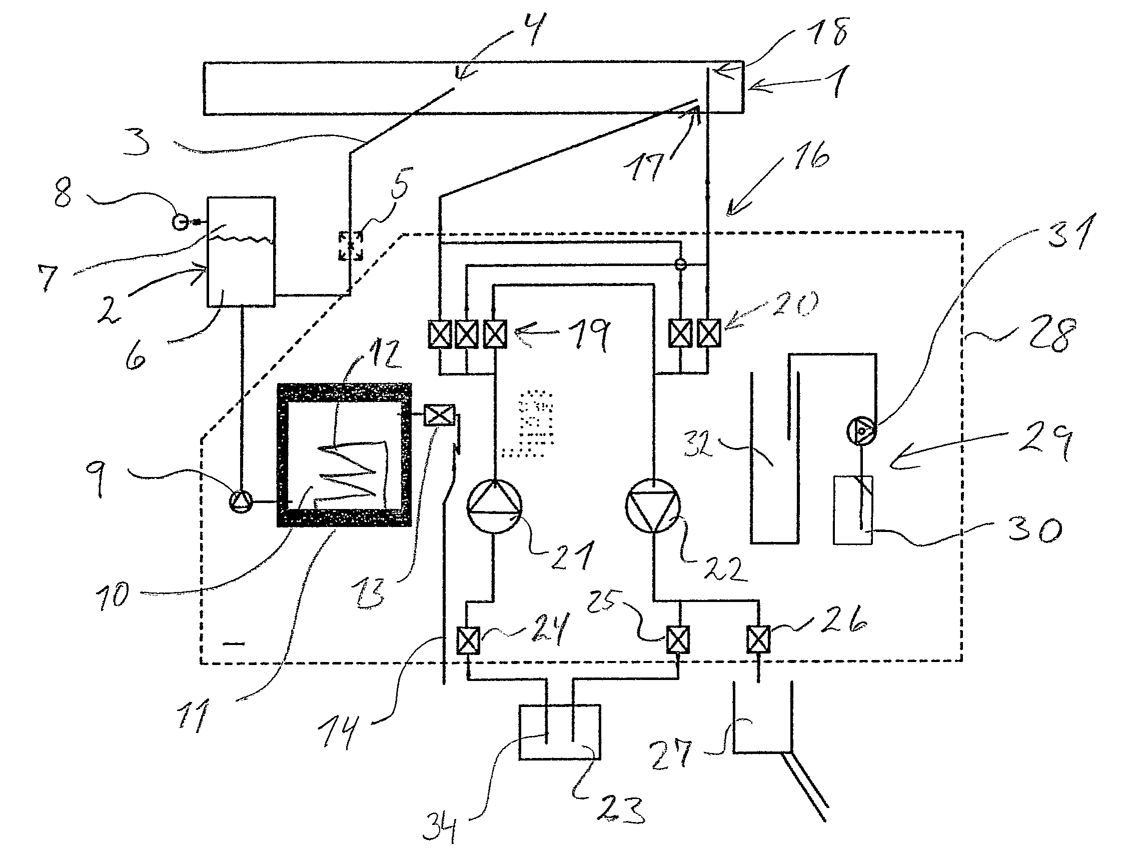
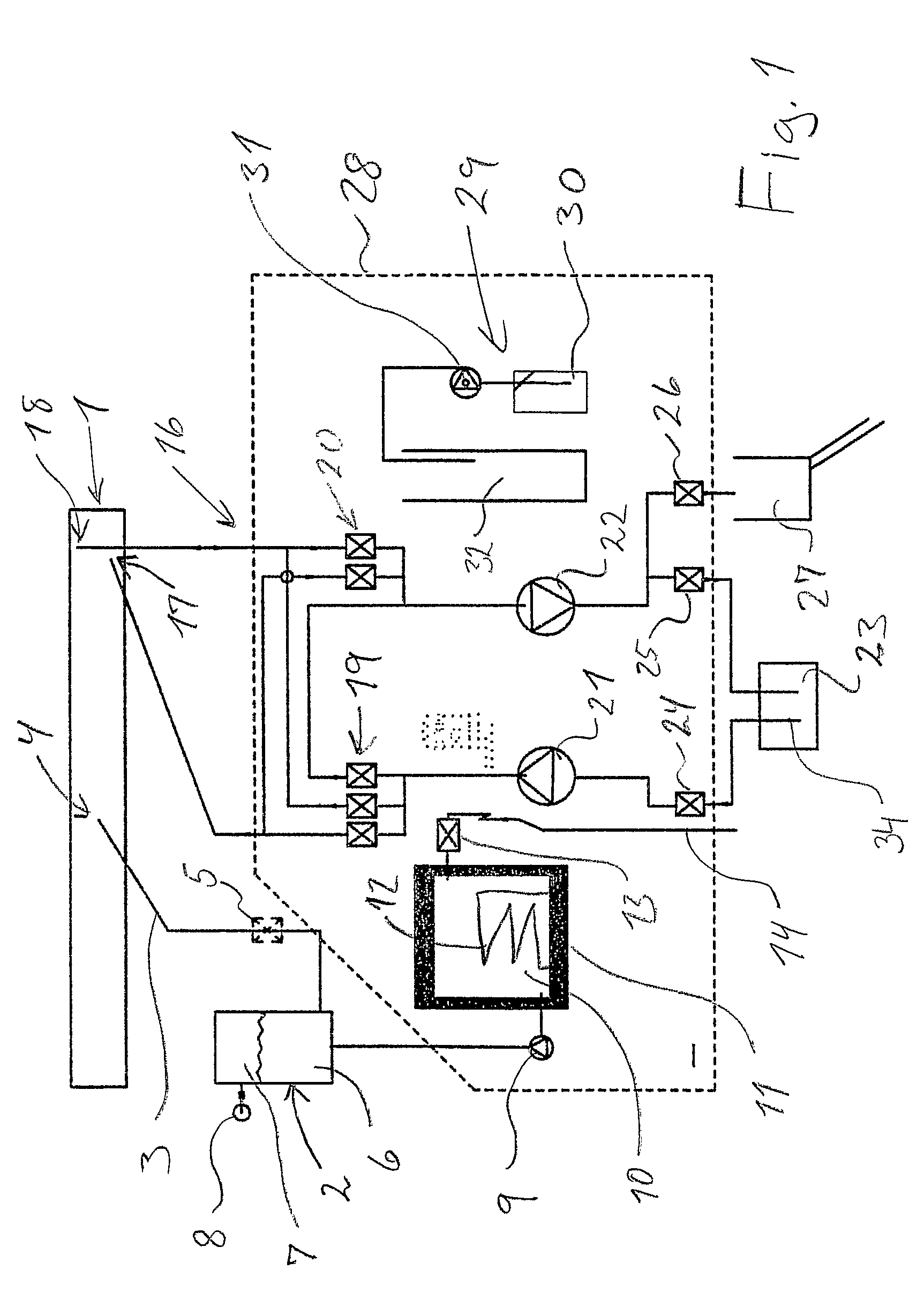
[0061]In FIG. 1 is shown a doctor blade 1 intended for flexographic printing. A hydrophore 2 is connected with an injection opening 4 in the chamber via a connecting line 3. In the line 3 is inserted a valve 5 connecting the hydrophore with the chamber 1. In the hydrophore is provided cleaning liquid 6 and air 7. The hydrophore is connected with a standard pressurised air system and a high-pressure liquid pump 9. The high-pressure liquid pump connects the hydrophore 2 with a storage tank 10 which is provided with insulation 11 and a heater 12. Via a valve 13, the storage tank 10 is connected with a supply line 14 for cleaning liquid or cold / hot water. Alternatively, the connection line 14 is connected with an external liquid supply system, as for example a water tap.

[0062]FIG. 1 shows t...


PUM


Abstract

There is described a method and a system for cleaning an ink chamber (1) of a printing unit. The system includes a storage tank (10) which via a high-pressure pump (9) is connected with a hydrophore (2). In the hydrophore a high pressure is built up, and the hydrophore is connected with cleaning nozzles (40) via a valve (5). Thus it becomes possible to inject a shot of cleaning liquid into the chamber by switching the valves (5). The cleaning nozzles are preferably designed as a mushroom-shaped plug (40) with a stem (41) which is mounted in the chamber wall and which has a circular domed top (43) of elastic, resilient material. When injecting cleaning liquid, the elastic plug will spray cleaning liquid out into the chamber, and after shutting off the pressure, there will be a self-closing effect.

Description

[0001]This application claims the benefit of Danish Application No. PA 2004 00448 filed Mar. 19, 2004 and PCT / DK2005 / 000170 filed Mar. 12, 2005, which are hereby incorporated by reference in their entirety.BACKGROUND OF THE INVENTION[0002]The present invention concerns a method for cleaning the ink chamber of a printing unit, preferably a chamber in a doctor blade, where pressurised cleaning liquid is sprayed into the chamber through at least one cleaning nozzle.[0003]The invention also concerns a system for cleaning an ink chamber of a printing unit, preferably a chamber in a doctor blade, including at least one cleaning nozzle through which pressurised cleaning liquid is sprayed into the chamber.[0004]The invention furthermore concerns a cleaning nozzle for use in a chamber in a doctor blade, where pressurised cleaning liquid is injected into the chamber through at least one such nozzle.[0005]The prior art comprises a method for supplying a printing unit with cleaning liquid for c...

Claims


Application Information

Patent Timeline
Patent Type & Authority Patents(United States)
IPC IPC(8): F04B41/06B41F31/02B41F35/00B41L41/00F16K15/14F16K24/04
CPCB41F31/027F16K15/148B41F35/00Y10T137/3127B41L41/00F16K24/04
Inventor GYDESEN, ERIK
Owner TRESU ANLAEG
Why Eureka
Try Eureka