
Blood loss detection for hemodialysis system

Inactive Publication Date: 2010-01-05
MCCALL KENNETH SHAWN
View PDF6 Cites 73 Cited by
  • Summary
  • Abstract
  • Description
  • Claims
  • Application Information

AI Technical Summary

Benefits of technology

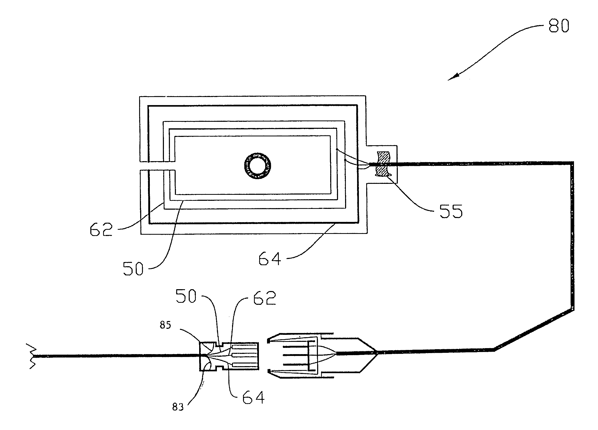
[0019]The present invention is also modular in design so that the device may be quickly installed, quickly removed, and replaced as desired. The multi-conductor cable extends from the patch and terminates in a male modular connector which cooperates with a female modular connector which is, in turn, connected to a multi-conductor cable from the hemodialysis machine and the component elements thereof.

Problems solved by technology

Even if done in the supervision of medical professionals, a patient cannot be monitored every minute.
There have been reports of the return line becoming accidentally dislodged or pulled from the access site in the patient.
If the dialysis machine and its accompanying pump continue to operate, blood will be drawn from the patient but will not properly be returned to the patient.
If this condition continues, the patient can suffer loss of blood and even death.
While the hemodialysis machines have existing pressure sensing devices, they may not sense the condition if the blood continues to pump.
Additionally, if the patient is sleeping or if medical personnel are not constantly observing the entire procedure, blood loss may occur until it is discovered.
The Van Antwerp devices can not be installed once the return line is attached to the patient.
If the Van Antwerp device were to be placed prior to inserting the needle into the patient, the sterile field of the access site would be compromised, possibly resulting in an infection of the patient's blood.

Method used


Image

  • Blood loss detection for hemodialysis system
  • Blood loss detection for hemodialysis system
  • Blood loss detection for hemodialysis system

Examples


Embodiment Construction

[0029]The embodiments discussed herein are merely illustrative of specific manners in which to make and use the invention and are not to be interpreted as limiting the scope of the instant invention.

[0030]While the invention has been described with a certain degree of particularity, it is to be noted that many modifications may be made in the details of the invention's shape, construction and the arrangement of its components without departing from the spirit and scope of this disclosure. It is understood that the invention is not limited to the embodiments set forth herein for purposes of exemplification.

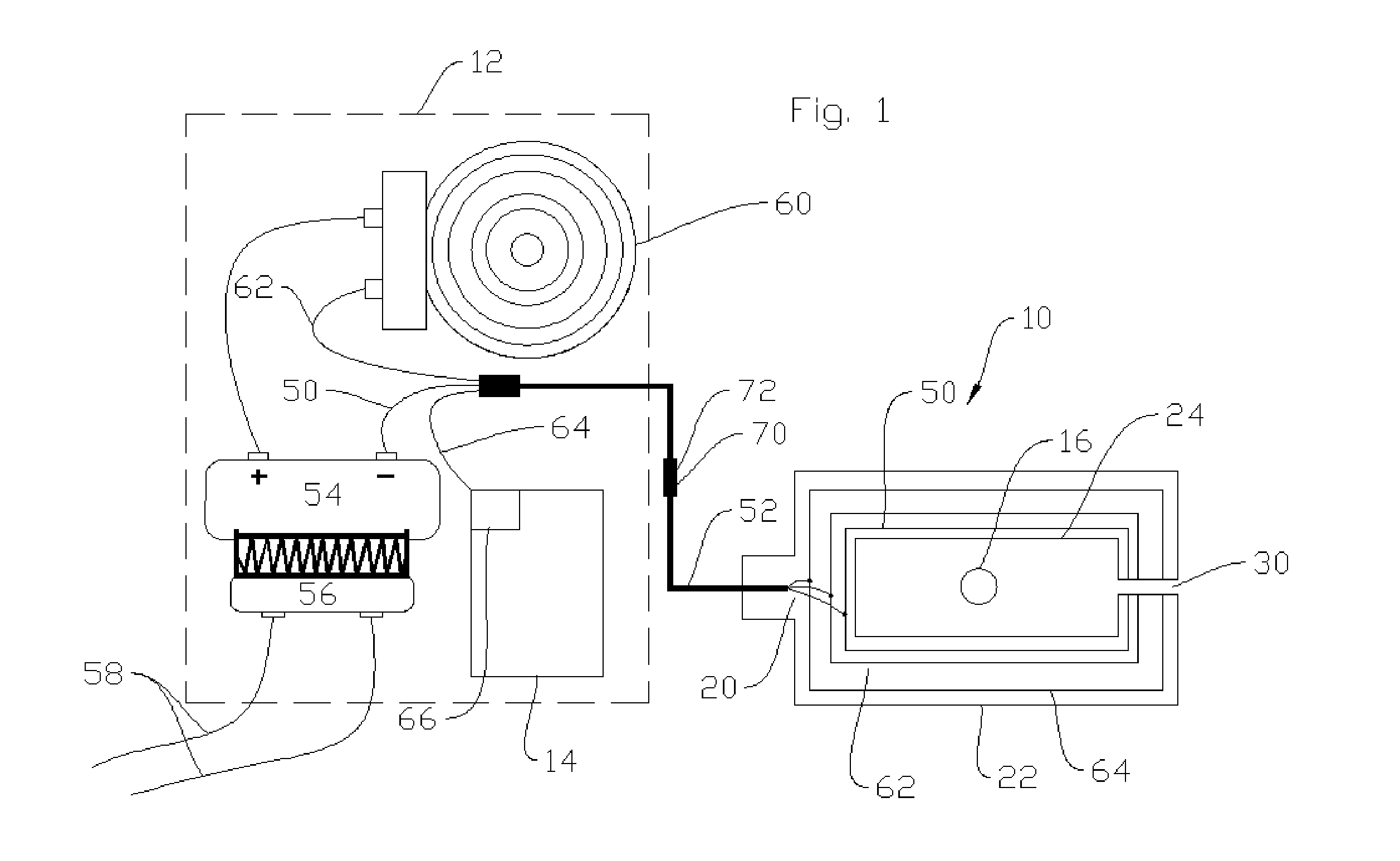
[0031]Referring to the drawings in detail, FIG. 1 illustrates a simple diagrammatic view of a blood loss detection device 10 constructed in accordance with the present invention.

[0032]The blood loss detection device 10 is utilized with and operates along with a hemodialysis system, represented by dashed lines 12.

[0033]Hemodialysis machines and the hemodialysis procedure are both we...


PUM


Abstract

A blood loss detection device for a hemodialysis system having a blood intake line, a dialysis machine including a pump, with the dialysis machine in communication with the blood intake line, and a blood return line in communication with the dialysis machine. The detection device includes a patch having an exterior edge and an opening through the patch forming a target for receipt of the return blood line. A slit through the patch extends between the exterior edge and the opening. A primary loop circuit terminates at two ends at the slit. An early warning alarm circuit loop terminates at two ends at the slit. An emergency shut-down circuit loop terminates at two ends at the slit. A modular connector connects the patch to an alarm activated by the early warning alarm circuit and to a switch mechanism activated by the shut-down circuit in order to shut down the dialysis machine and the pump.

Description

BACKGROUND OF THE INVENTION[0001]1. Field of the Invention[0002]The present invention relates to a blood loss detection device and method for a hemodialysis system.[0003]2. Prior Art[0004]Hemodialysis is a known medical procedure through which a person's blood is cleansed of toxins. Hemodialysis is often prescribed when the kidneys no longer function properly for any of a number of reasons. Hemodialysis is typically performed at a hospital or dialysis center although there is interest in and a trend toward home use. In a dialysis treatment, the patient is connected to a hemodialysis machine via two tubes. The first tube is a blood intake tube and is responsible for removing blood from the patient and transferring it to the machine. When the blood enters the machine, it is cleaned via semi-permeable filters and then is pumped back to the patient through a blood return tubing. Before hemodialysis can be done, a doctor must make an entrance, often called an “access”, into the patient's...

Claims


Application Information

Patent Timeline
IPC IPC(8): A61B5/0265A61B5/00A61M5/00
CPCA61M1/3653A61M1/3656A61M2205/18A61M2205/3317A61M2205/3561A61M2205/3592A61M1/3655A61M1/3659
Inventor MCCALL, KENNETH SHAWN
Owner MCCALL KENNETH SHAWN
Learn More