Implicit feature recognition for a solid modeling system

a solid modeling system and feature recognition technology, applied in the field of computer-aided design (cad), can solve problems such as laborious, inaccurate geometry correction, and physical incorrect parts, and design engineers may be required to spend an enormous amount of time and effor

Active Publication Date: 2010-01-05
DASSAULT SYST SOLIDWORKS CORP
View PDF7 Cites 8 Cited by
  • Summary
  • Abstract
  • Description
  • Claims
  • Application Information

AI Technical Summary

Problems solved by technology

Often the design engineer discovers that the feature order results in the generation of a physically incorrect part.
The design engineer is then burdened with deleting and re-creating portions of the part or the entire part, re-ordering the features that constitute the part by manipulating one or more feature locations in the overall historical order of features, or in some other manner, which may be tedious, correcting the inaccurate geometry.
The design engineer may be required to spend an enormous amount of time and effort during the 3D modeling process controlling the feature order and the feature order's affect on the final geometric representation of a part.
Moreover, while building a part, the order in which a design engineer should introduce features and direct the system to perform operations is not always intuitive.
Due to the problem of introducing features in a particular order, modeling a part may require a great deal of planning and expertise.
The ordering problem is present throughout the modeling process.
The difficulty of the ordering problem may increase as the modeling process progresses because as a part becomes more complex, the design engineer has more difficulty determining the correct feature order.
Moreover, features are connected to each other in complex ways and real-world parts have multiple features.
Having the ability to change the sequence in which features are generated does not address the problem of propagating incorrect geometry.
For example, re-ordering fillets to correct the geometry of one corner may cause the geometry in a second corner positioned at the opposite end of one or more of the re-ordered fillets to become incorrect.

Method used


Image

  • Implicit feature recognition for a solid modeling system
  • Implicit feature recognition for a solid modeling system
  • Implicit feature recognition for a solid modeling system

Examples


Embodiment Construction

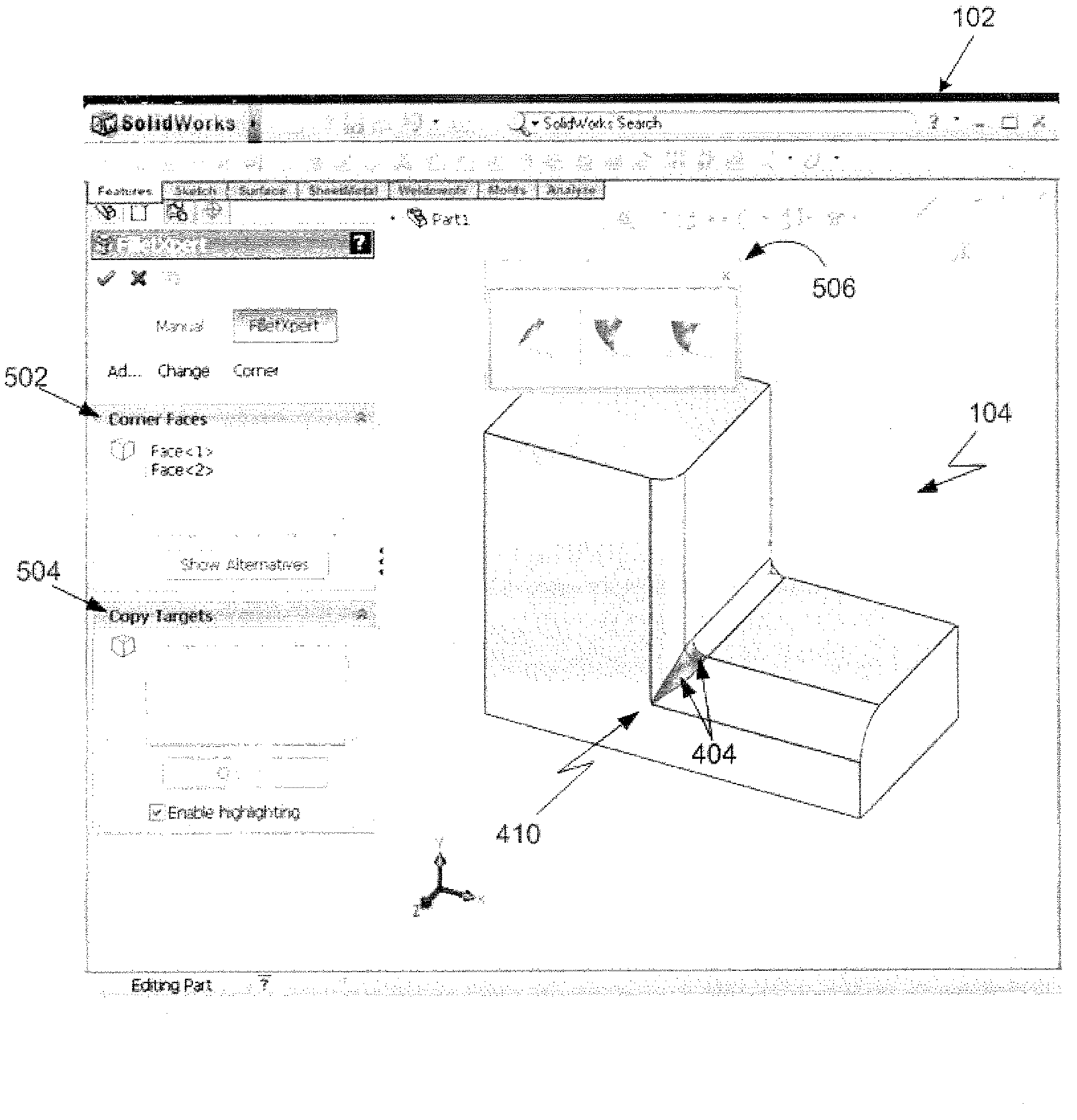
[0029]The present invention recognizes that a collection of features that are positionally interrelated form an implicit feature, creates a new feature to replace geometry generated by the collection of features, and gives a user explicit control over the new feature. Hereinafter, the new feature that generates geometry that replaces geometry generated by the collection of features will be referred to as an explicit feature.

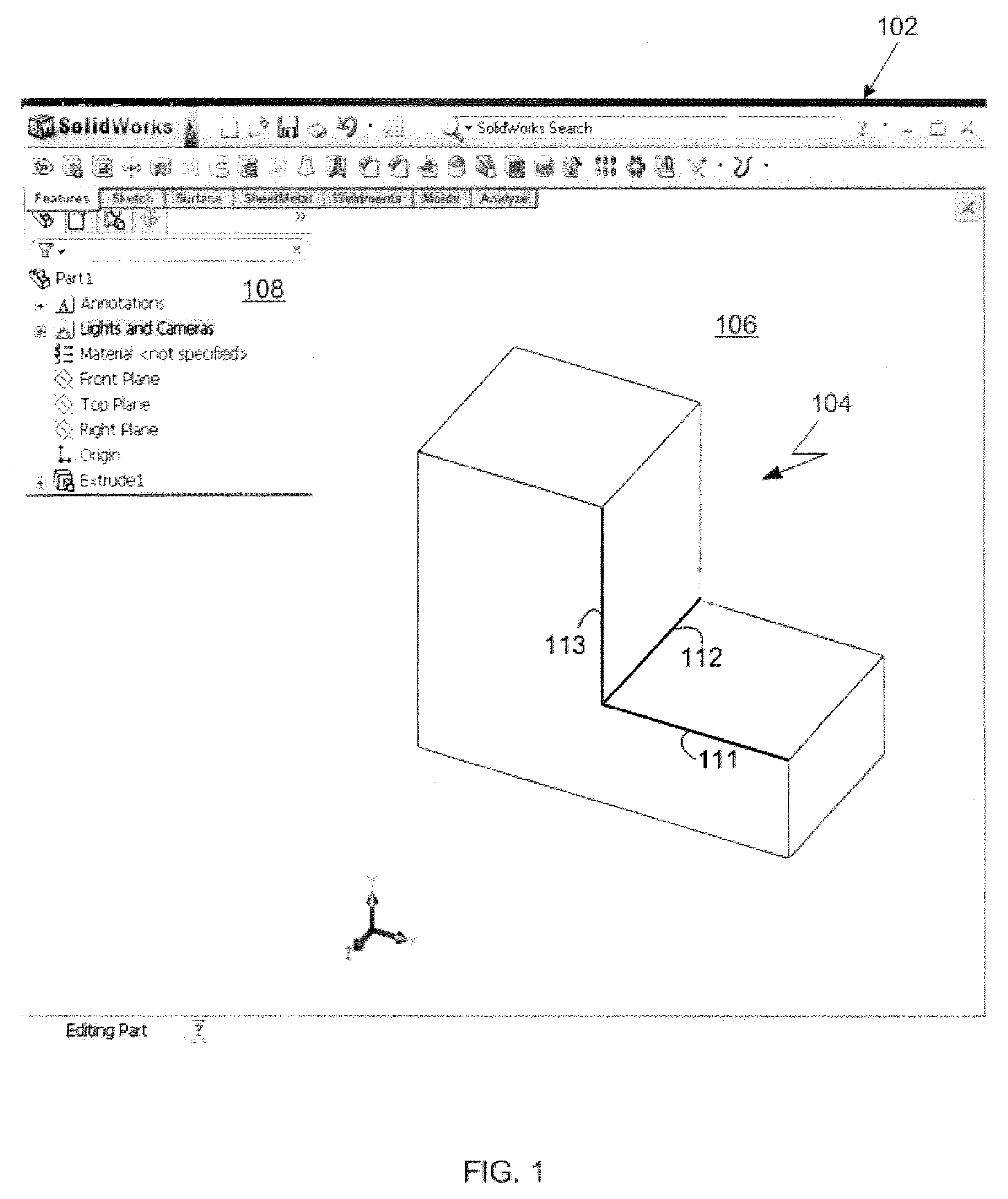
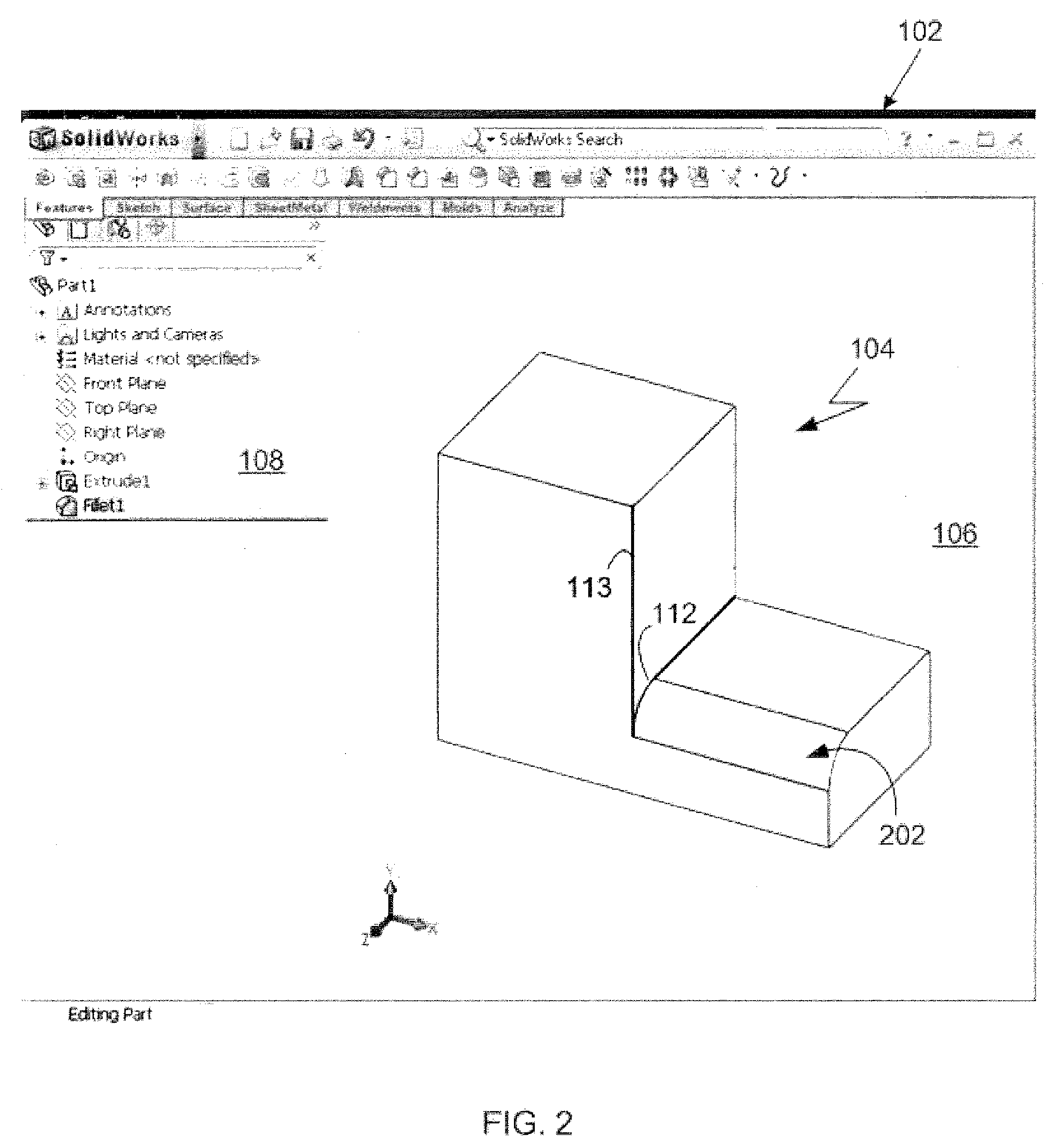
[0030]Referring now to FIG. 1, a window 102 displayed on a computer monitor is shown. The window 102 is generated by modeling software executed by a computerized modeling system, an example of which is later shown with reference to FIG. 9. The window 102 is a conventional computer-generated window that can be programmed by one of ordinary skill in the art using conventional, commercially available, software programming tools, such as those available from Microsoft Corporation of Redmond, Wash.

[0031]A computer-generated 3D model 104 is displayed within a modeling ...


PUM


Abstract

Creating an explicit feature used for construction of a computer-aided design model includes recognizing that model features form an implicit feature, presenting variations of the implicit feature, selecting one of the variations of the implicit feature, and creating the explicit feature. The explicit feature produces geometry that gives rise to the selected variation of the implicit feature. The computer-aided design model is constructed by generating the explicit feature after generating the model features that form the implicit feature.

Description

FIELD[0001]This application relates to Computer-Aided Design (CAD), and more particularly, to the recognition of implicit features and the creation of explicit features in 3D feature-based CAD modeling systems.BACKGROUND OF THE INVENTION[0002]Computer-aided design (CAD) software allows a user to construct and manipulate complex three-dimensional (3D) models. A number of different modeling techniques can be used to create a 3D model. One such technique is a solid modeling technique, which provides for topological 3D models where the 3D model is a collection of interconnected topological entities (e.g., vertices, edges, and faces). The topological entities have corresponding supporting geometrical entities (e.g., points, trimmed curves, and trimmed surfaces). The trimmed surfaces correspond to the topological faces bounded by the edges. CAD systems may combine solid modeling and other modeling techniques, such as parametric modeling techniques. Parametric modeling techniques can be us...

Claims


Application Information

Patent Timeline
Patent Type & Authority Patents(United States)
IPC IPC(8): G06T15/00
CPCG06T17/10
Inventor ROTHSTEIN, SAUL J.SIEGEL, ROBERT M.CHIN, RICARDO W.GIBSON, MARK G.
Owner DASSAULT SYST SOLIDWORKS CORP
Why Eureka
Try Eureka