Nanocrystal doped matrixes

a technology of nanocomposites and nanocomposites, applied in the field of nanocomposite matrixes, can solve the problems of poor power efficiency, poor color rendering, and number of critical shortfalls

Active Publication Date: 2010-01-12
SAMSUNG ELECTRONICS CO LTD
View PDF83 Cites 250 Cited by
  • Summary
  • Abstract
  • Description
  • Claims
  • Application Information

AI Technical Summary

Benefits of technology

[0163]As discussed above, the size of the nanocrystals can be tailored by selecting specific semiconductor materials and then generating and processing the nanocrystals until the desired size is attained. In the various embodiments of the present invention, the nanocrystals will suitably be between about 1 nm and about 20 nm in size. More suitably, between about 1 nm and about 10 nm, between about 1 nm and about 4 nm and most suitably between about 1 nm and about 3 mm. As shown in FIG. 16, using a constant loading volume of ZnS nanocrystals (22% by volume) in silicone, the percent transmittance of light can be tailored from between about 5% to about 100% (i.e. percent that is scattered can be tailored from between about 95% to about 0%). It is a significant advantage of the present invention that by generating nanocrystals that are between about 1 nm to about 4 nm, less than about 50% of the incident light is scattered by the nanocomposites of the present invention. As shown in FIG. 16, by creating nanocrystals that are between about 1 nm and about 3 nm, scattering of less than 20%, approaching 15%, 10%, 5% and 0%, can be achieved. As demonstrated in FIG. 17, a silicone nanocomposite, comprising 3 nm ZnS nanocrystals and a layer with a 3 mm pathlength will scatter less than about 50% (i.e. transmit more than about 50%) of the incident light over the wavelength range 350 nm to 700 nm, scatter less than about 30% over the wavelength range 400 nm to 700 nm and scatter less than about 15% over the wavelength range 500 nm to 700 nm.
[0164]In the formation of the nanocomposites of the present invention, two critical issues are: (1) achieving high miscibility of the nanocrystals in the host matrix, and (2) prevention of aggregation of the nanocrystals at a high concentration. Aggregation results in quenching of the emission, hence a lowering of the amount of light transmitted, as well as light scattering from the aggregates. Tuning the index of refraction of the overall composite layer also occurs at different nanocrystals loading densities. Since the nanocrystals have a refractive index of about 2.5 to about 3 and the host matrix is about 1.5 to about 2, matching of the refractive index of the LED substrate (typically sapphire or SiC) will eliminate an optical interface and losses from total internal reflection.
[0165]As part of this approach, several issues are addressed, including determination of whether the necessary loading densities in the nanocomposites as determined by simulations are achieved; whether the nanocrystals are homogenously embedded in the host matrix with no (or minimized) aggregation or phase separation so that a high quantum yield is retained and scattering is prevented; whether the index of refraction of the composite layer can be tuned by adjusting the loading density (e.g., gradient) of nanocrystals in the host matrix; whether refractive indices close to the LED substrate are achieved and what the projected effect on the light extraction efficiency is; and at the nanocrystal loading density for refractive index matching, what is the layer thickness of the composite layer necessary to reach an optical density at the excitation wavelength to yield the optimized emission profile determined by the simulations. It can also be determined whether this thickness is compatible with low cost, thin film processing (e.g., thicknesses <1-2 microns).
[0166]In order to accomplish this, a tailored, miscibility-enhancing ligand can be designed to bind, associate, coordinate, attach or conjugate to a nanocrystal, and to allow for controlled mixing and miscibility in the host matrix. The performance characteristics, including quantifying the effects on the internal quantum efficiency and light extraction efficiency are measured on nanocomposites of various loading densities and thicknesses.Surface Chemistry Modification
[0167]Dispersion of nanocrystals in a host matrix can be controlled by minimizing phase separation and aggregation that can occur when mixing the nanocrystals into the matrixes. A basic strategy of the present invention is to design a novel 3-part ligand, in which the head-group, tail-group and middle / body-group can each be independently fabricated and optimized for their particular function, and then combined into an ideally functioning complete surface ligand (see FIG. 18; see FIG. 19 for an example ligand). As shown in FIG. 18, head group 1804 is selected to bind specifically to the semiconductor or other material of the nanocrystal (e.g., can be tailored and optimized for CdSe, ZnS, a metal, or any other nanocrystal material). Tail group 1800 is designed to interact strongly with the matrix material and be miscible in the solvent utilized (and can, optionally, contain a linker group to the host matrix) to allow maximum miscibility and loading density in the host matrix without nanocrystal aggregation. Middle or body group 1802 is selected for specific electronic functionality (e.g., charge isolation).
[0168]This multipart ligand strategy has been used for the fabrication of high loading density, non-fluorescent, polymer-CdSe nanorod composites in the development of hybrid inorganic-organic nanocomposite solar cells. In certain embodiments of the present invention, significant modifications to the ligand are made due to differences in the two applications. Specifically, the ligand is designed to be charge insulating (rather than charge conducting) and to provide retention of nanocrystal photoluminescence as well as to be compatible with a completely different matrix type (inorganic rather than organic polymers) and nanocrystal material type and shape.

Problems solved by technology

Unfortunately, existing rare-earth activated phosphors or halophosphates, which are currently the primary source for solid-state down-conversion, were originally developed for use in fluorescent lamps and cathode ray tubes (CRTs), and therefore have a number of critical shortfalls when it comes to the unique requirements of SSWL.
As such, while some SSWL systems are available, poor power efficiency ($200 / kilolumen (klm)) limit this technology to niche markets such as flashlights and walkway lighting.
Furthermore, LEDs often suffer from reduced performance as a result of internal reflection of photons at the chip / coating interface.
Currently these coatings are made by using an inorganic or organic coating that has a very different refractive index than the base material (i.e., the chip), which results in a detrimental optical effect due to the refractive index mismatch at the interface between the two materials.
The resulting LED structure suffers loss of light at the chip / compliant polymer interface due to the lower refractive index of the polymer coating in relation to the LED.
However, if the refractive index of the compliant layer is increased, even greater loss will occur due at the high refractive index / low refractive index interface between the compliant polymer and the hard shell polymer due to internal reflection.
There are several critical factors which result in poor power efficiencies when using traditional inorganic phosphors for SSWL.
These include: total internal reflection at the LED-chip and phosphor layer interface resulting in poor light extraction from the LED into the phosphor layer; poor extraction efficiency from the phosphor layer into the surroundings due to scattering of the light generated by the phosphor particles as well as parasitic absorption by the LED chip, metal contacts and housing; broad phosphor emission in the red wavelength range resulting in unused photons emitted into the near-IR; and poor down-conversion efficiency of the phosphors themselves when excited in the blue wavelength range (this is a combination of absorption and emission efficiency).
While efficiencies improve with UV excitation, additional loss due to larger Stokes-shifted emission and lower efficiencies of LEDs in the UV versus the blue wavelength range makes this a less appealing solution overall.
As a result, poor efficiency drives a high effective ownership cost.
The cost is also significantly impacted from the laborious manufacturing and assembly process to construct such devices, for example the heterogeneous integration of the phosphor-layer onto the LED-chip during packaging (DOE and Optoelectronics Industry Development Association “Light emitting diodes (LEDs) for general illumination,” Technology Roadmap (2002)).
However, many of the current filters allow photon emission from the blue end of the spectrum, thus limiting the quality of the white LED.
The performance of the devices also suffer from poor color rendering due to a limited number of available phosphor colors and color combinations that can be simultaneously excited in the blue.
While some development of organic phosphors has been made for SSWL, organic materials have several insurmountable drawbacks that make them unlikely to be a viable solution for high-efficiency SSWL.
These include: rapid photodegradation leading to poor lifetime, especially in the presence of blue and near-UV light; low absorption efficiency; optical scattering, poor refractive index matching at the chip-interface, narrow and non-overlapping absorption spectra for different color phosphors making it difficult or impossible to simultaneously excite multiple colors; and broad emission spectra.

Method used


Image

  • Nanocrystal doped matrixes
  • Nanocrystal doped matrixes
  • Nanocrystal doped matrixes

Examples


example 1

Core / shell Nanocrystal Synthesis

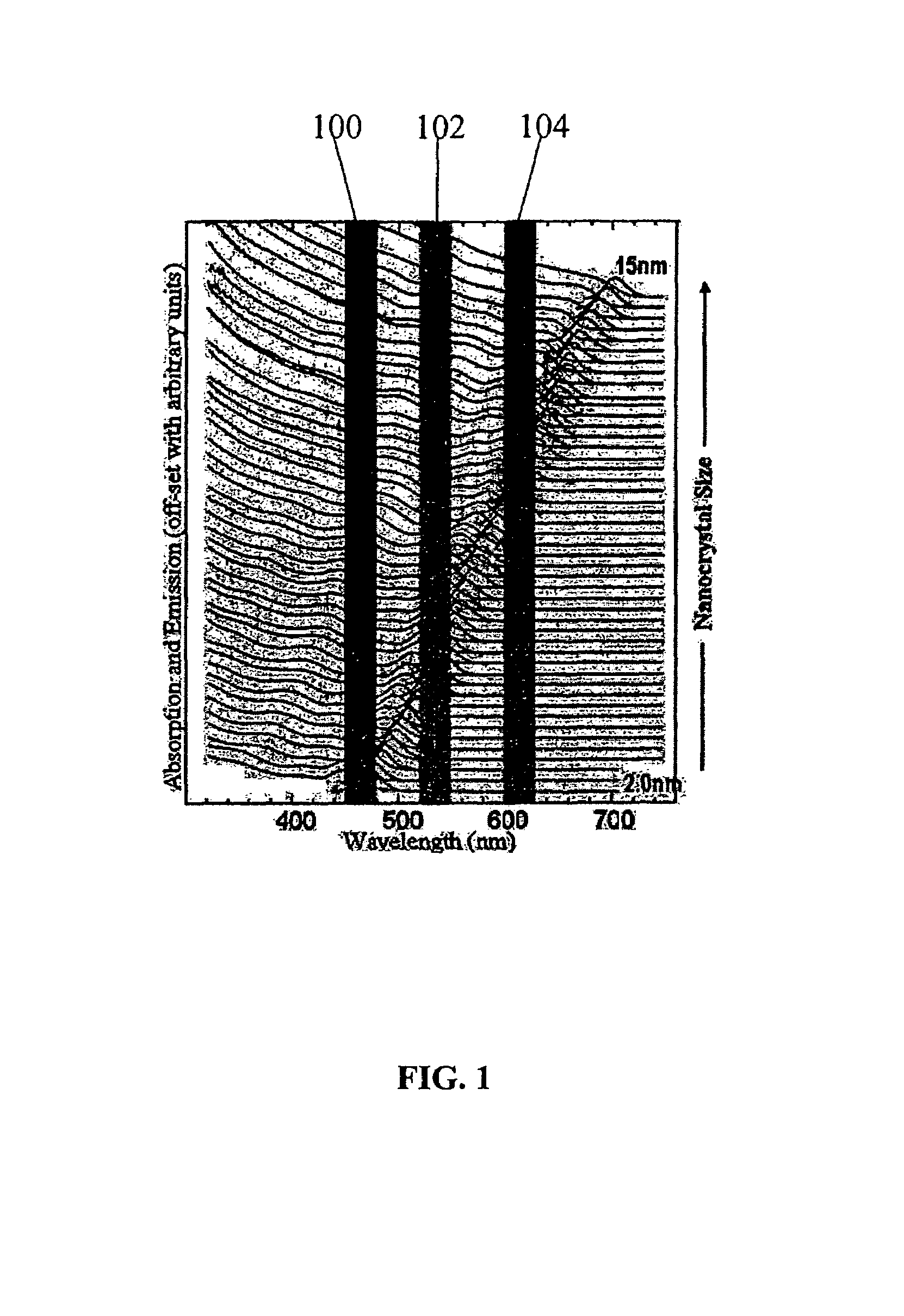
[0255]Suitable nanocrystal synthesis procedures include fabricating nanocrystal samples with specific spectral characteristics matched to those prescribed by the theoretical models of the present invention. This can include fabricating nanocrystals with tunable sizes and size distributions (e.g., sizes ranging from 1-20 nm in diameter producing emission peak wavelengths tunable between 460 and 640 nm with FWHM tunable from about 15 to about 100 nm). This in turn is used to synthesize nanocrystal mixtures identified by simulations that have the optimal emission characteristics. The simulation and core / shell nanocrystal procedure is typically performed in an iterative process.

[0256]Type I core-shell nanocrystals of CdSe / ZnS (core / shell) can be synthesized by a two step process using a solution phase method, first with the fabrication of the core material followed by growth of the shell.

Core Synthesis

[0257]Stock solutions are prepared of Se powder dissol...

example 2

ZnS Nanocrystal Synthesis

[0261]In the order listed, add the following to a 50 mL 3-neck round bottom flask:

[0262]1. Zn(acetate)2: 76.5 mg Lot#12727BC

[0263]2. Stearic Acid: 484 mg Lot#06615MA

[0264]3. Tri-n-octylphosphine oxide (TOPO): 4.07 g Lot#21604LA

[0265]In a glove box prepare the following:

[0266]3.9 g of distilled tri-n-octylphosphine (TOP) (#35-111) in 5 mL syringe;

[0267]116.4 mg of stock solution 02-190 (bis(trimethylsilyl)sulfide (TMS2S):TOP) in 1 mL syringe; and

[0268]One 40 mL septa cap vial with 5.0 mL of MeOH

[0269]Place reactor under vacuum

[0270]Heat to 120° C.

[0271]Once at 120° C., allow to sit for 20 minutes

[0272]Place reactor under argon

[0273]Slowly inject TOP from 5 mL syringe

[0274]Change set point temperature to 250° C.

[0275]Once at 250° C., immediately inject the stock solution 02-190 (bis(trimethylsilyl)sulfide (TMS2S):TOP) from 1 mL syringe

[0276]Grow with temperature at 250° C. for 2 minutes

[0277]Remove the heating mantle and allow reaction to cool to 50° C.

[0278]A...

example 3

Carboxylic Acid-Silicone Ligand Synthesis

[0282]General Methods

[0283]All manipulations were carried out with strict exclusion of air and moisture by using Schlenk technique under an atmosphere of dry nitrogen, unless otherwise stated. THF, toluene, chloroform-d1 and toluene-d8 were dried over activated 4 A Molecular Sieves and de-gassed by three freeze-pump-thaw cycles. 4-pentenoic acid and 1,1,1,3,5,5,5-heptamethyltrisiloxane were purchased from Aldrich (St. Louis, Mo.), distilled and stored in a storage flask using Schlenk technique before use. Heptamethyl cyclotetrasiloxane and 1,1,1,3,3,5,5-heptamethyl trisiloxane were purchased from Gelest (Morrisville, Pa.), distilled and stored in a storage flask using Schlenk technique before use. Karstedt's catalyst or platinum divinyl tetramethyl disiloxane complex, 2.1 to 2.4% in xylenes, was purchased from Gelest, stored in the glove box and used without further purification. All products were stored in the glove box. NMR chemical shift d...


PUM

PropertyMeasurementUnit
temperatureaaaaaaaaaa
sizeaaaaaaaaaa
sizeaaaaaaaaaa

Abstract

Matrixes doped with semiconductor nanocrystals are provided. In certain embodiments, the semiconductor nanocrystals have a size and composition such that they absorb or emit light at particular wavelengths. The nanocrystals can comprise ligands that allow for mixing with various matrix materials, including polymers, such that a minimal portion of light is scattered by the matrixes. The matrixes of the present invention can also be utilized in refractive index matching applications. In other embodiments, semiconductor nanocrystals are embedded within matrixes to form a nanocrystal density gradient, thereby creating an effective refractive index gradient. The matrixes of the present invention can also be used as filters and antireflective coatings on optical devices and as down-converting layers. Processes for producing matrixes comprising semiconductor nanocrystals are also provided. Nanostructures having high quantum efficiency, small size, and / or a narrow size distribution are also described, as are methods of producing indium phosphide nanostructures and core-shell nanostructures with Group II-VI shells.

Description

CROSS-REFERENCE TO RELATED APPLICATIONS[0001]This application is a continuation-in-part of U.S. patent application Ser. No. 11 / 034,216, filed Jan. 13, 2005, entitled “Nanocrystal Doped Matrixes” by Parce et al., which issued on May 20, 2008, as U.S. Pat. No. 7,374,807, and which claims priority to and benefit of provisional U.S. Patent Application No. 60 / 536,962, filed Jan. 15, 2004, and U.S. Provisional Patent Application No. 60 / 635,784, filed Dec. 15, 2004, the full disclosures of which are hereby incorporated by reference in their entirety for all purposes.STATEMENT AS TO RIGHTS TO INVENTIONS MADE UNDER FEDERALLY SPONSORED RESEARCH AND DEVELOPMENT[0002]Portions of this invention may have been made with United States Government support under Department of Energy grant DE-FG02-04ER84020 entitled “High Efficiency Nanocomposite White Light Phosphors.” As such, the United States Government may have certain rights in the invention.FIELD OF THE INVENTION[0003]The present invention relat...

Claims


Application Information

Patent Timeline
Patent Type & Authority Patents(United States)
IPC IPC(8): C09K11/02H01L33/50
CPCB82Y20/00C01B19/007C01G9/08C09K11/02C09K11/565C09K11/70C09K11/883G02B1/11G02B3/0087B82Y30/00Y10T428/2993C01P2002/72C01P2002/84C01P2004/04C01P2004/64C01P2004/80C01P2004/84G02B2207/101H01L33/502Y10S977/783Y10T428/2995Y10T428/2991Y10T428/2982B82B1/00B82B3/00
Inventor PARCE, J. WALLACEBERNATIS, PAULDUBROW, ROBERTFREEMAN, WILLIAM P.GAMORAS, JOELKAN, SHIHAIMEISEL, ANDREASQIAN, BAIXINWHITEFORD, JEFFERY A.ZIEBARTH, JONATHAN
Owner SAMSUNG ELECTRONICS CO LTD
Why Eureka
Try Eureka