DNP apparatus

a technology of dynamic nuclear polarization and apparatus, which is applied in the direction of using reradiation, geological measurements, magnetic measurements, etc., can solve the problems of lack of sensitivity of conventional magnetic resonance imaging and nmr spectroscopy, and inability to retain the polarization of protons, so as to achieve further control and reduce heat radiation

Inactive Publication Date: 2010-01-12
OXFORD INSTR IND PROD +1
View PDF12 Cites 15 Cited by
  • Summary
  • Abstract
  • Description
  • Claims
  • Application Information

AI Technical Summary

Benefits of technology

[0010]We have devised a new form of coolant sub-assembly which can cool a sample within a DNP working region by flowing coolant past the sample while the subassembly is constructed such that a sample holder assembly can be withdrawn through the second end of the inner bore tube opposite to the first end into which it was inserted. This means that the hyper polarized sample can be rapidly transferred from the DNP working region into an NMR working region if the coolant sub-assembly is mounted coaxially with the NMR apparatus.
[0013]Preferably, therefore, the auxiliary coolant supply path is defined by one or more capillaries extending from the coolant supply path the corresponding at least one aperture in the inner bore tube wall. This structure enables the coolant flow to be accurately determined, and further control can be achieved by providing a heater coupled to one or more of the capillaries.
[0014]A further problem which can arise when the coolant sub-assembly is mounted on an NMR apparatus is that heat may pass up through the inner bore tube due to convection and radiation since the NMR apparatus bore will be at room temperature. At the same time, however, it must be possible to withdraw the sample holder through the second end of the inner bore tube. To deal with this, the sub-assembly preferably further comprises one or more resilient baffles extending across the inner bore tube, between the first and the second end of the inner bore tube apertures, for reducing heat radiation and being sufficiently flexible to allow movement of a sample holder past the or each baffle. The baffles should be made of a suitable reflective material such as mylar.

Problems solved by technology

Conventional magnetic resonance imaging (MRI) and NMR spectroscopy often lack sensitivity due to the very low polarizations of the nuclear spins of the materials used.
A problem with these known systems is that, although the sample will retain polarization of carbon because the hyper polarization of carbon relaxes slowly in liquid, polarization of protons is not retained since this relaxes very fast.
This is a drawback because most high resolution NMR is carried out on protons.

Method used


Image

  • DNP apparatus
  • DNP apparatus
  • DNP apparatus

Examples


Embodiment Construction

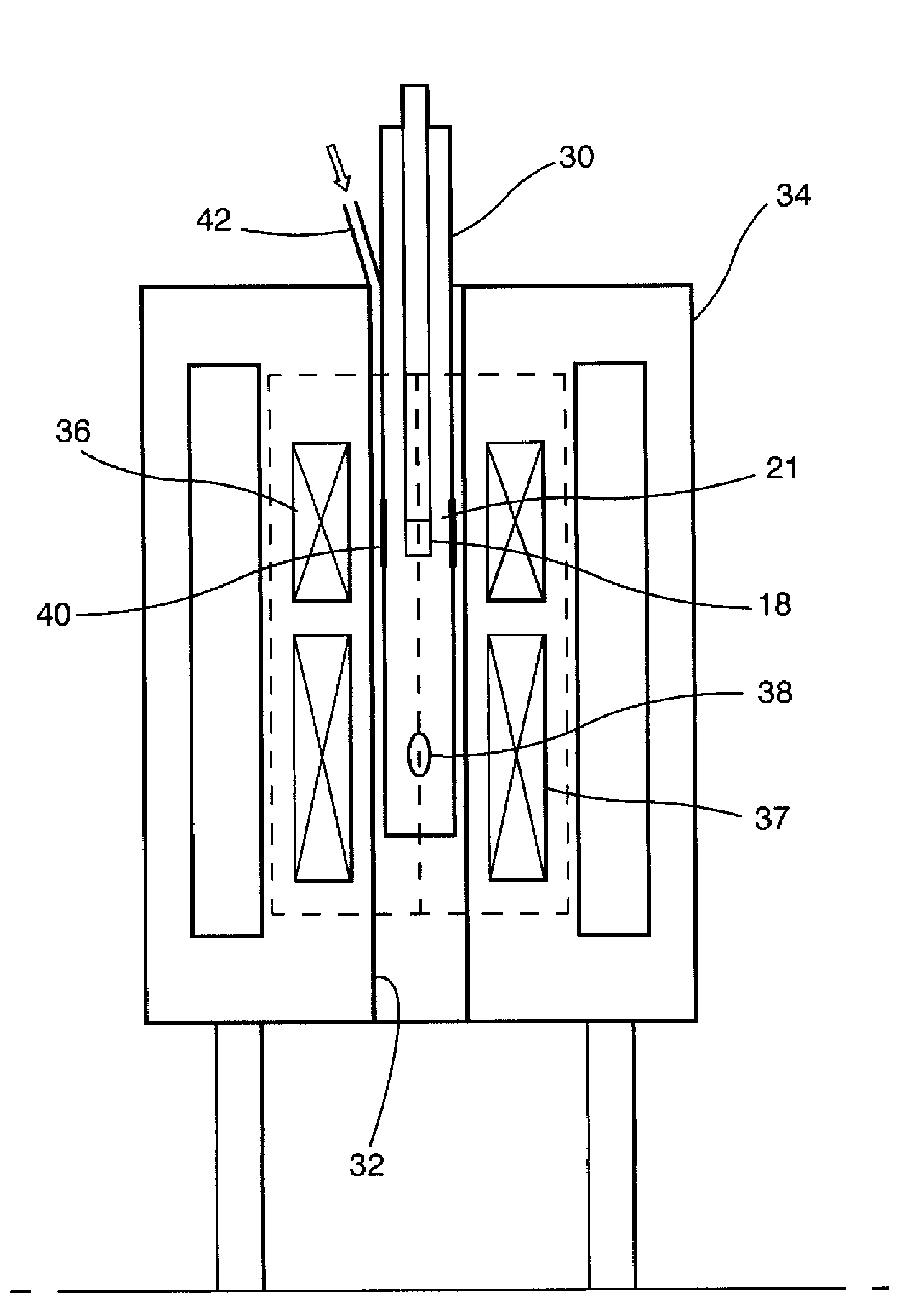
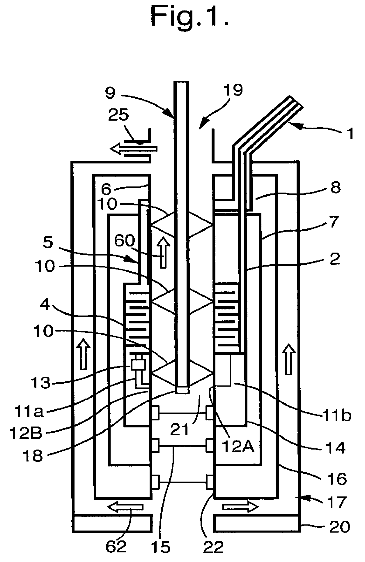
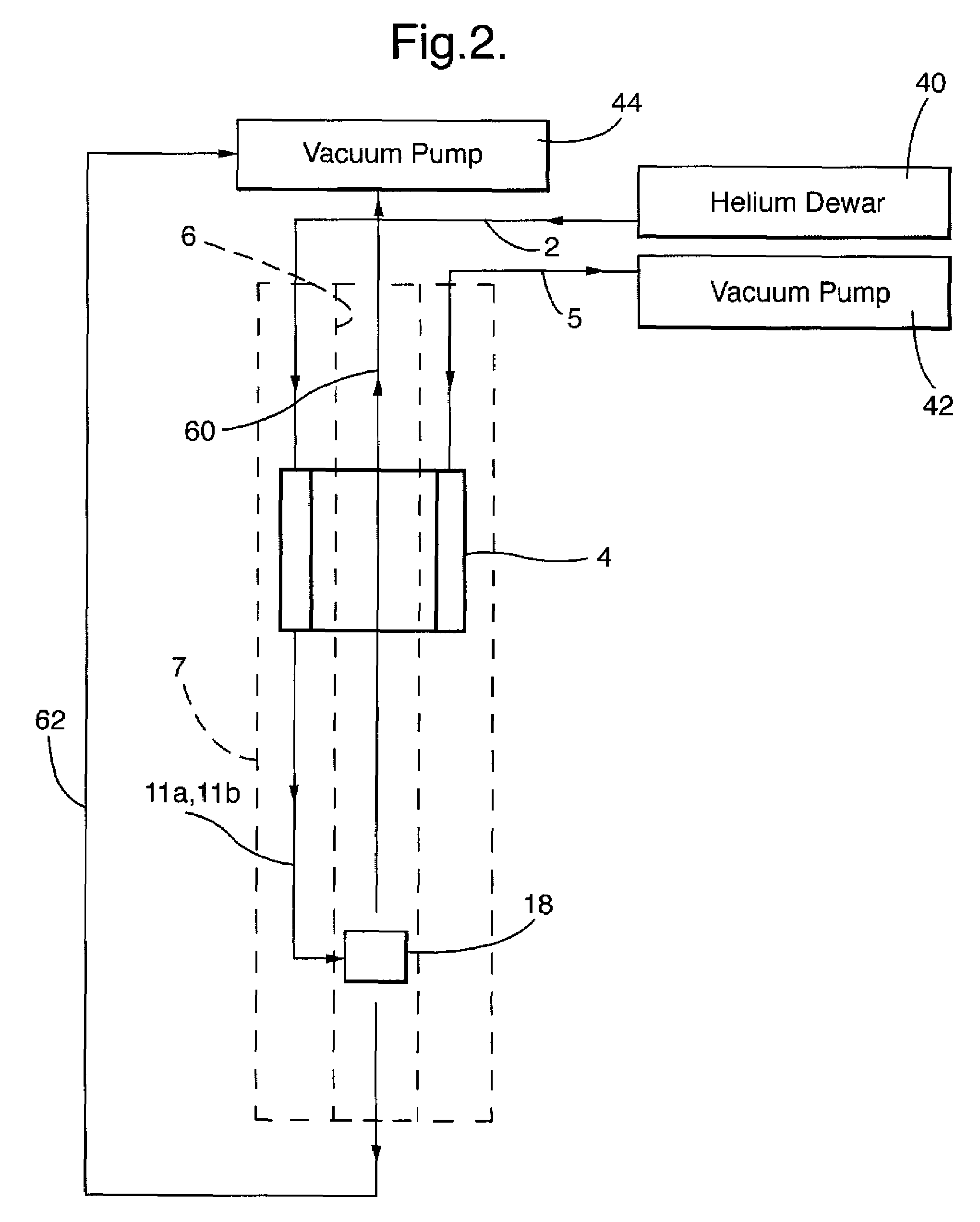
[0020]The coolant sub-assembly (or cryo-insert) shown in FIG. 1 comprises an inner bore tube 6 surrounded by a plurality of concentric jackets including inner and outer radiation shields 14 and 7, an outer vacuum chamber wall 16, and an outer sock 17. In some cases, only one radiation shield may be needed. The inner bore tube 6 is vertically oriented and has an upper, first opening closed by a seal 19 through which a sample insertion rod 9 can be removably inserted. The rod 9 has a sample holder 18 removably mounted at its lower end, the sample holder being shown in FIG. 1 located at a DNP working region indicated by a shaded area 21. The spaces between the inner bore tube 6 and the radiation shield 7 and between the radiation shields 7 and 16 are evacuated.

[0021]A primary liquid helium coolant supply path is used to provide primary cooling to the inner bore tube 6. This supply path comprises a capillary 2 connected at its upper end to a storage dewar 40 (FIG. 2) via a siphon 1, whe...


PUM


Abstract

A coolant sub-assembly is provided for use in a DNP apparatus. The sub-assembly comprises a plurality of concentric jackets surrounding an inner bore tube having first and second opposed ends. The jackets are adapted to inhibit heat flow to the inner bore tube, a DNP working region being defined within the inner bore tube where a DNP process will be performed on a sample in the DNP working region. A coolant supply path extends adjacent an outer surface of the inner bore tube at the DNP working region in order to cool said outer surface, whereby a sample holder assembly can be inserted through the first end of the inner bore tube to bring a sample holder into the DNP working region and can be moved through the second end of the inner bore tube. An auxiliary coolant supply path supplies coolant to a sample, located in use in the sample holder at the DNP working region, through at least one aperture in the inner bore tube wall at the DNP working region. One or both ends of the inner bore tube opens into a coolant waste path for conveying coolant away from the inner bore tube, and wherein the coolant, auxiliary coolant, and waste paths are coupled to pumping means in use to cause coolant to pass along the coolant, auxiliary coolant and waste paths.

Description

CROSS-REFERENCE TO RELATED APPLICATIONS[0001]This application claims the benefit under 35 U.S.C. § 119 of European Patent Application No. 07114986.8, filed on Aug. 24, 2007, in the European Patent Office (EPO), the disclosure of which is incorporated herein by reference in its entirety.FIELD OF THE INVENTION[0002]The invention relates to DNP (dynamic nuclear polarization) apparatus.DESCRIPTION OF THE PRIOR ART[0003]In the field of nuclear magnetic resonance (NMR) analysis, it is necessary to detect nuclear spins of materials of interest. Conventional magnetic resonance imaging (MRI) and NMR spectroscopy often lack sensitivity due to the very low polarizations of the nuclear spins of the materials used. To reduce this problem, it has become common to enhance the polarization by using a variety of techniques, one of which is dynamic nuclear polarization (DNP). In DNP, a sample is placed in a high strength magnetic field and held at low temperature while being irradiated with microwave...

Claims


Application Information

Patent Timeline
Patent Type & Authority Patents(United States)
IPC IPC(8): G01V3/00
CPCG01R33/282G01R33/31G01R33/62G01R33/445G01R33/4808
Inventor SLADE, ROBERT ANDREWTOWNSEND, MARTIN CHARLESSTRANGE, DANIELSTABLES, GARYKOCKENBERGER, WALTER FRIEDRICH
Owner OXFORD INSTR IND PROD
Why Eureka
Try Eureka