Wave front sensing method and apparatus

a wave front and sensing technology, applied in the field of wave front sensing, can solve the problems of reducing the field of applications to environments and expensive instruments, and achieve the effects of improving performance, in particular speed and image quality, and reliable wave front sensing performan

Active Publication Date: 2010-01-19
LYNCEE TEC
View PDF1 Cites 192 Cited by
  • Summary
  • Abstract
  • Description
  • Claims
  • Application Information

AI Technical Summary

Benefits of technology

[0044]One of the strengths of wave front sensors is their ability to achieve sub-wavelength, high resolution and high precision imaging and metrology, thanks to an access to the phase of a radiation. As a result of this high sensitivity wave front sensors are also highly sensitive to external perturbations. Moreover a high degree of precision is required for the realization and assembly of all components embedded in a wave front sensor. This results in expensive instruments and reduces the field of applications to environments showing relatively low levels of perturbations.
[0102]The use of DWFO improves the performance, e.g. speed and precision, and the ease of use of instruments for wave front sensing. The use of DWFO may result into technical simplifications and costs reductions at the instrumental level. The use of DWFO widens the field of applications of wave front sensing techniques.

Problems solved by technology

This results in expensive instruments and reduces the field of applications to environments showing relatively low levels of perturbations.

Method used


Image

  • Wave front sensing method and apparatus
  • Wave front sensing method and apparatus
  • Wave front sensing method and apparatus

Examples


Embodiment Construction

General Description of the System

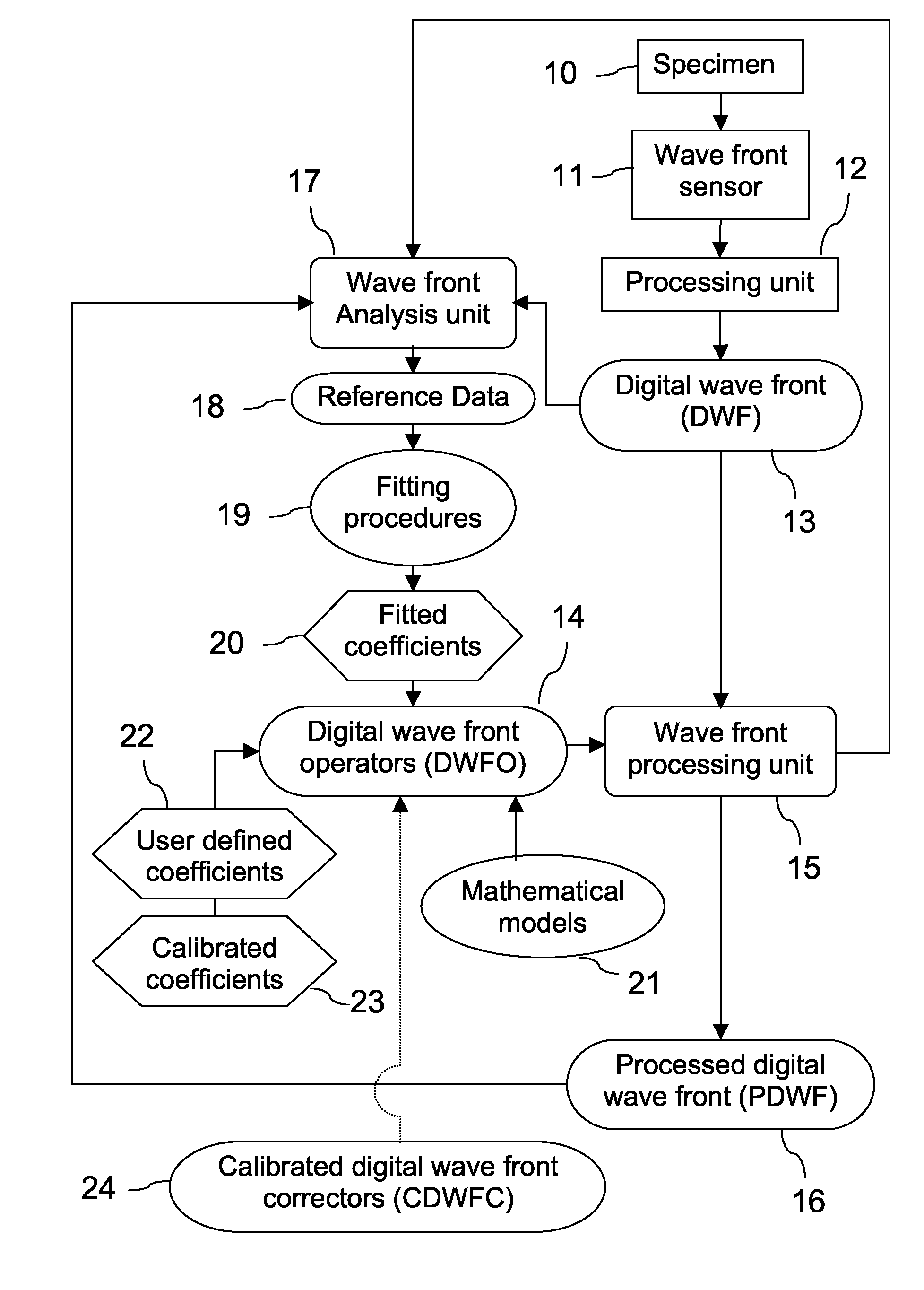
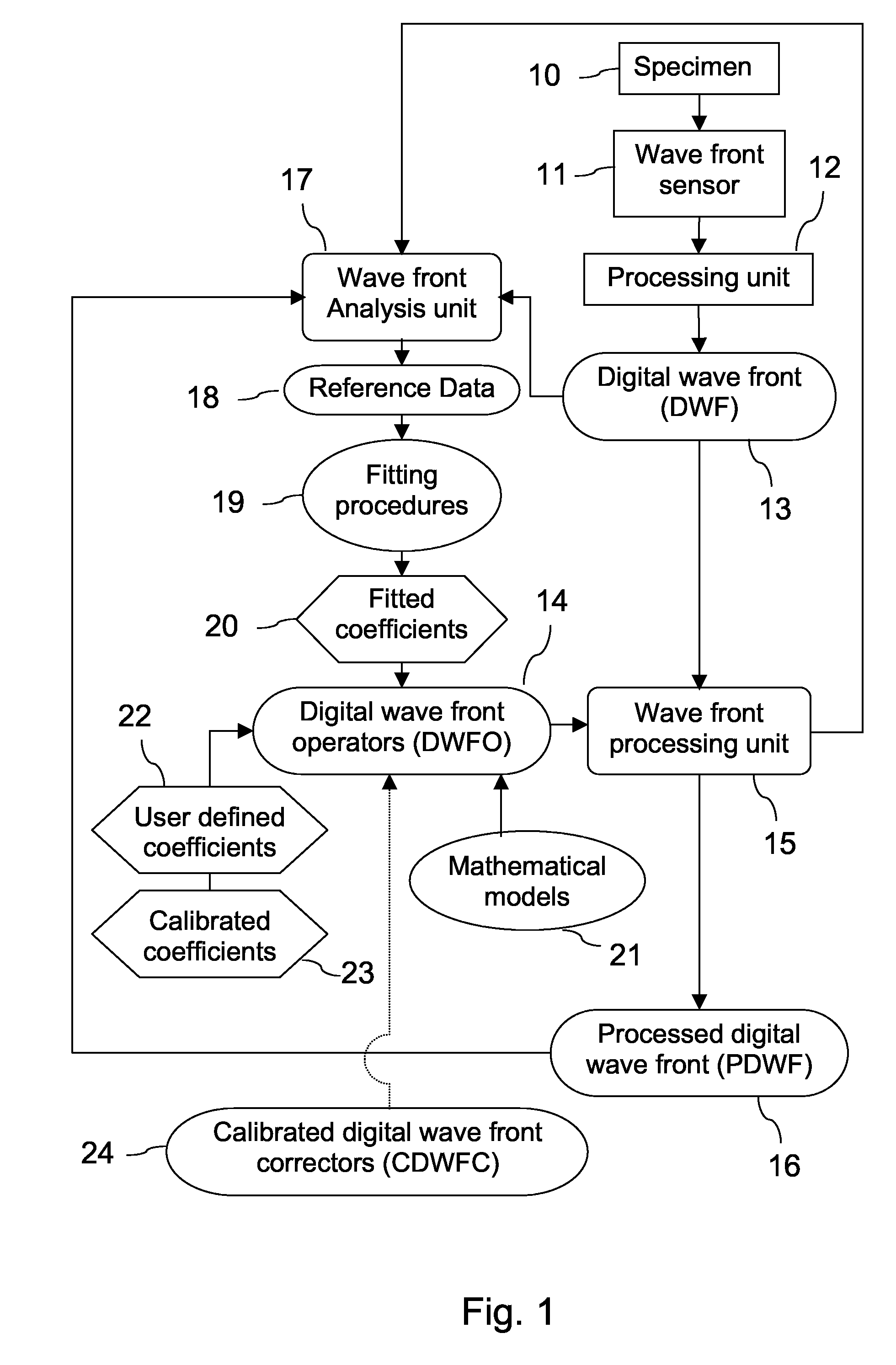
[0139]As shown in FIG. 1, a wave front sensing system according to the present invention comprises a specimen (10) investigated by a wave front sensor (11). The wave front sensor (11) is connected to a processing unit (12) providing a digital wave front DWF (13). The digital wave front DWF (13) is processed by at least one digital wave front operator DWFO (14), thanks to a wave front processing unit (15), in order to produce a processed digital wave front PDWF (16). A wave front analysis unit (17) is connected to at least one of: the digital wave front DWF (13), the wave front processing unit (15), the processed digital wave front PDWF (16). The wave front analysis unit (17) provides reference data (18). At least one fitting procedure (19) is applied on the reference data (18) to provide fitted coefficients (20). At least one digital wave front operator DWFO (14) is defined using at least one mathematical model (21) and using at least one of: the fit...


PUM


Abstract

A new way of mixing instrumental and digital means is described for the general field of wave front sensing. The present invention describes the use, the definition and the utility of digital operators, called digital wave front operators (DWFO) or digital lenses (DL), specifically designed for the digital processing of wave fronts defined in amplitude and phase. DWFO are of particular interest for correcting undesired wave front deformations induced by instrumental defects or experimental errors. DWFO may be defined using a mathematical model, e.g. a polynomial function, which involves coefficients. The present invention describes automated and semi-automated procedures for calibrating or adjusting the values of these coefficients. These procedures are based on the fitting of mathematical models on reference data extracted from specific regions of a wave front called reference areas, which are characterized by the fact that specimen contributions are a priori known in reference areas. For example, reference areas can be defined in regions where flat surfaces of a specimen produce a constant phase function. The present invention describes also how DWFO can be defined by extracting reference data along one-dimensional (1D) profiles. DWFO can also be defined in order to obtain a flattened representation of non-flat area of a specimen. Several DWFO or DL can be combined, possibly in addition with procedures for calculating numerically the propagation of wave fronts. A DWFO may also be defined experimentally, e.g. by calibration procedures using reference specimens. A method for generating a DWFO by filtering in the Fourier plane is also described. All wave front sensing techniques may benefit from the present invention. The case of a wave front sensor based on digital holography, e.g. a digital holographic microscope (DHM), is described in more details. The use of DWFO improves the performance, in particular speed and precision, and the ease of use of instruments for wave front sensing. The use of DWFO results in instrumental simplifications, costs reductions, and enlarged the field of applications. The present invention defines a new technique for imaging and metrology with a large field of applications in material and life sciences, for research and industrial applications.

Description

[0001]This application is the US national phase of international application PCT / IB2006 / 050532 filed 17 Feb. 2006 which designated the U.S. and claims benefit of EP 05101374.6, dated 23 Feb. 2005, the entire content of which is hereby incorporated by reference.FIELD OF THE INVENTION[0002]The present invention is related in general to the field of wave front sensing and in particular to a method and apparatus involving specific means for the digital processing of wave fronts, in order to improve the performance, the ease of use, and the realization of wave front sensing systems.STATE OF THE ART[0003]Thanks to technologies for digital image acquisition, most imaging devices are now able to provide their results under a digital form, i.e. in a form that can be stored, processed, and presented with a computer. The majority of image sensors provide intensity images, which result from the conversion of the amplitude of a radiation into an electrical signal. When transmitted to a computer,...

Claims


Application Information

Patent Timeline
Patent Type & Authority Patents(United States)
IPC IPC(8): G03H1/02G03H1/10
CPCG01J9/02G03H1/0443G03H1/08G06T5/00G03H2001/0883G03H1/0866
Inventor COLOMB, TRISTANCUCHE, ETIENNEASPERT, NICOLASKUEHN, JONASMARQUET, PIERREDEPEURSINGE, CHRISTIANMONTFORT, FREDERICCHARRIERE, FLORIANMARIAN, ANCABOURQUIN, SEBASTIENEMERY, YVESHERMINJARD, SILVAIN
Owner LYNCEE TEC
Why Eureka
Try Eureka