Supercharge Your Innovation With Domain-Expert AI Agents!

Distance measuring system and method utilizing infrared radiation and ultrasonic wave

a technology of infrared radiation and distance measurement, applied in the direction of direction finders, instruments, measurement devices, etc., can solve the problem of reducing and achieve the effect of preventing the reduction of the measurement accuracy of the distance between the transmitter and the receiver

Inactive Publication Date: 2010-01-19
NEC DISPLAY SOLUTIONS LTD
View PDF20 Cites 5 Cited by
  • Summary
  • Abstract
  • Description
  • Claims
  • Application Information

AI Technical Summary

Benefits of technology

"The present invention provides a distance measuring system and method that can prevent errors in measuring the distance between a transmitter and a receiver. This is achieved by using a receiver that has a table showing the relationship between the arrival time of an ultrasonic wave and the required received signal strength for that arrival time. The transmitter emits both infrared radiation and ultrasonic waves, and the receiver compares the received ultrasonic wave with the required signal strength for the arrival time. The receiver calculates the distance to the transmitter based on the arrival time and the required signal strength. The system can also determine if the ultrasonic wave is a reflected wave by an obstacle based on the strength of the received wave. This prevents errors in calculating the distance due to reflected waves and ensures accurate measurements."

Problems solved by technology

However, the conventional distance measuring system as described above can erroneously determine the distance between the transmitter and receiver if an obstacle exists outside of a measurable area (area in which the system can measure the distance between the transmitter and receiver), and if, other than an ultrasonic wave which arrives directly at the receiver from the transmitter (hereinafter called the “direct wave”), as illustrated in FIG. 1, another ultrasonic wave from the transmitter arrives at the receiver after it has been reflected by the obstacle (hereinafter called the “reflected wave”).
This causes a problem of reduced measurement accuracy of the distance between the transmitter and receiver.

Method used


Image

  • Distance measuring system and method utilizing infrared radiation and ultrasonic wave
  • Distance measuring system and method utilizing infrared radiation and ultrasonic wave
  • Distance measuring system and method utilizing infrared radiation and ultrasonic wave

Examples


first exemplary embodiment

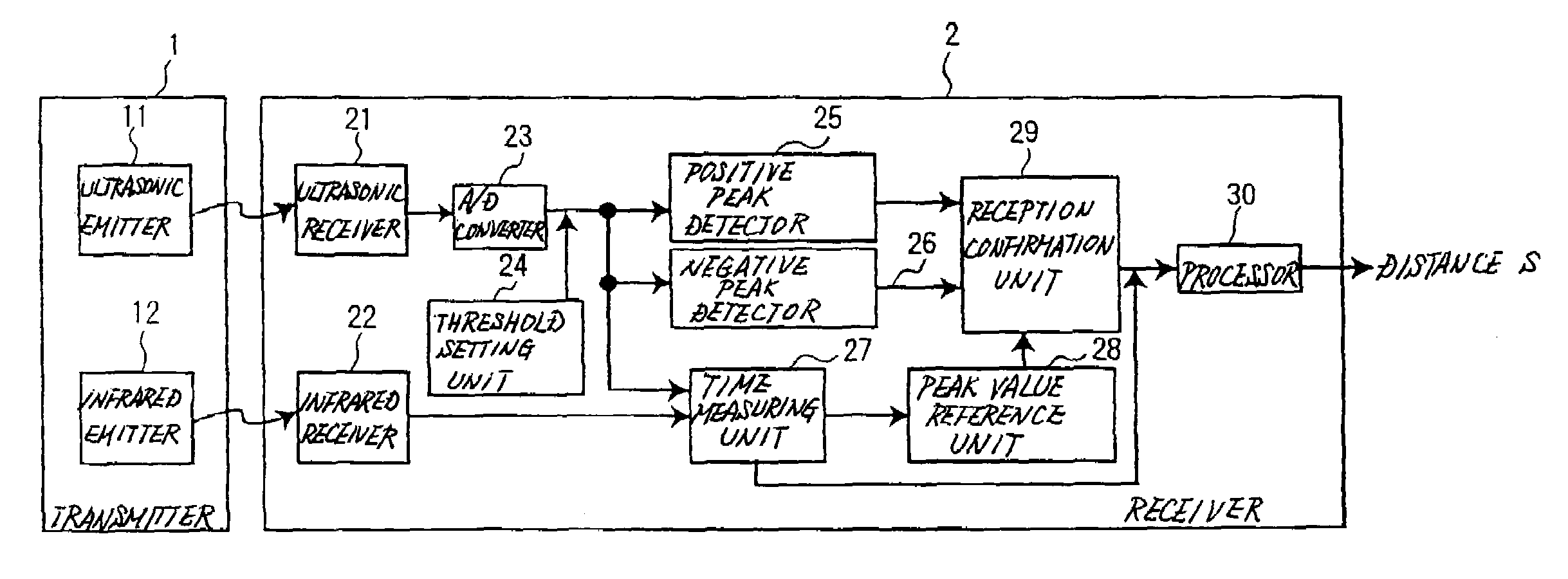
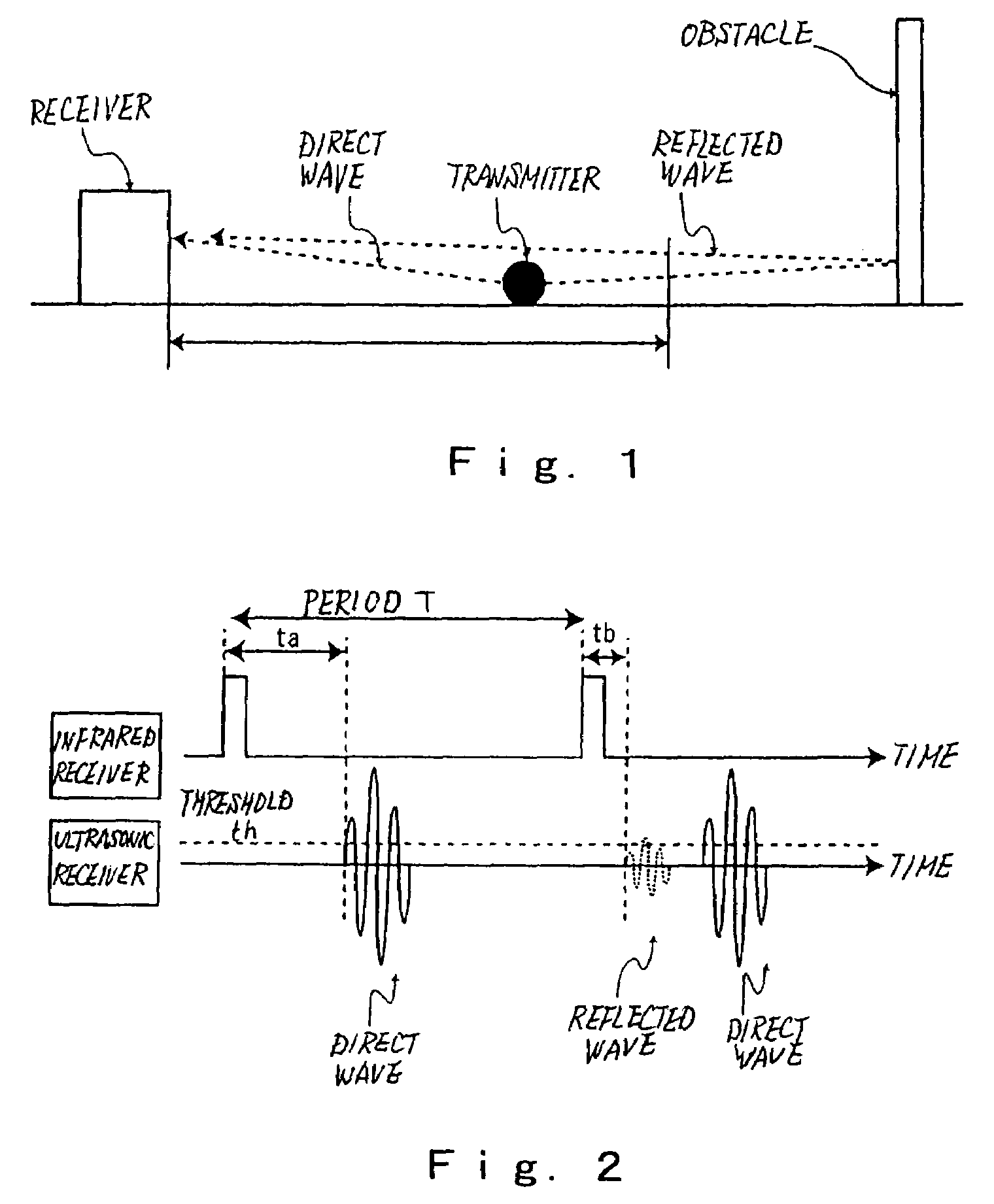
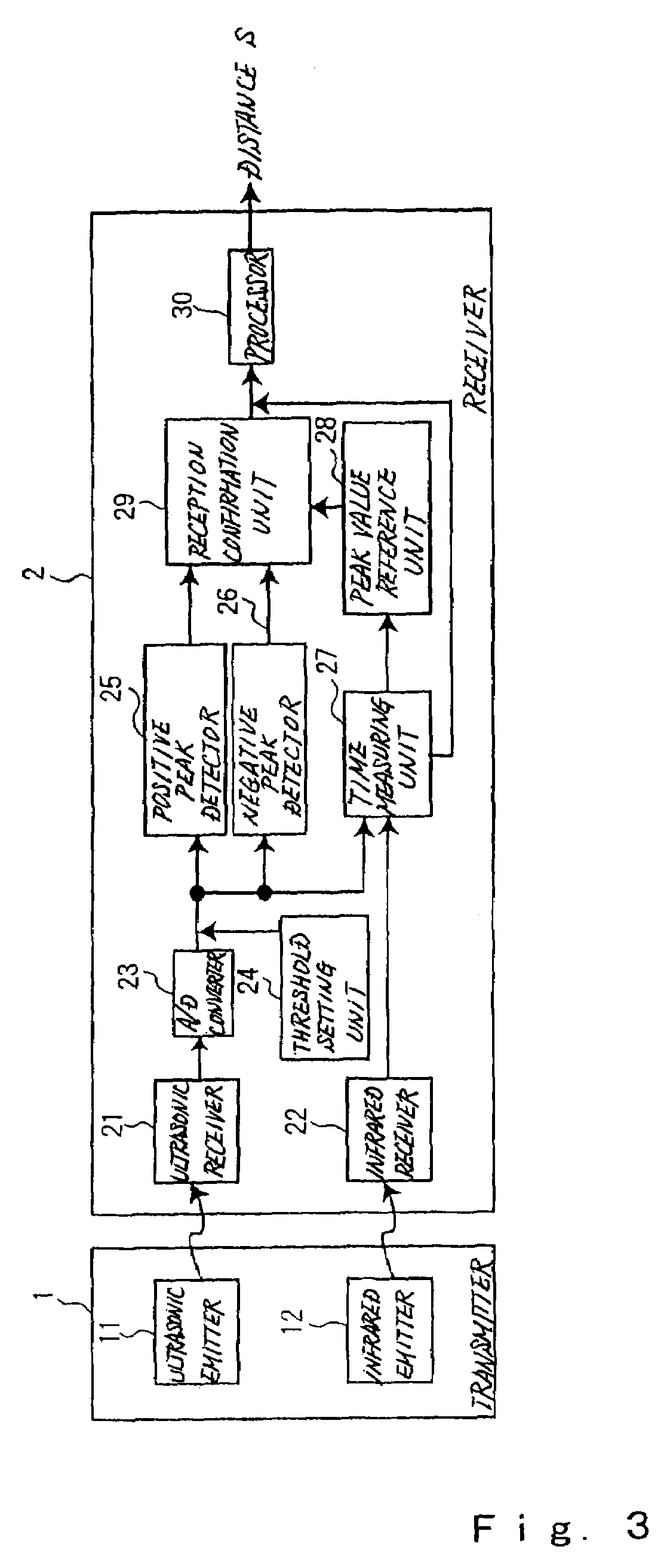
[0025]A distance measuring system of the present invention is similar to the conventional distance measuring system in that infrared radiation and an ultrasonic wave are simultaneously emitted from a transmitter for a fixed period, and the distance between the transmitter and receiver is measured based on the difference between the time the infrared radiation arrives at the receiver and the time the ultrasonic wave arrives at the receiver.

[0026]Generally, ultrasonic waves for use in measurement of distance are at a frequency of several tens kHz, and the strength of the ultrasonic wave received at a receiver attenuates depending on the traveling distance of the ultrasonic wave, i.e., from the time the receiver received an infrared radiation to the time the receiver receives the ultrasonic wave. Therefore, when a received ultrasonic wave presents a strength lower than a required value despite a short arrival time, the received ultrasonic wave can be determined to be a reflected wave f...

second exemplary embodiment

[0050]In a second exemplary embodiment, a receiver is previously provided with a table showing the relationship between the arrival time of the ultrasonic wave and a required received signal strength (expected minimum received signal strength) corresponding to the arrival time when the ultrasonic wave is directly received, in a manner similar to the first exemplary embodiment. Then, a threshold for use in determining whether or not an ultrasonic wave is received is updated with the value of the required received signal strength that corresponds to the arrival time retrieved from the table. By thus updating the threshold in accordance with the arrival time, since a reflected wave reception signal presents a received signal strength lower than the required value for the arrival time and therefore does not exceed the threshold, the reflected wave will never be used in the measurement of the distance.

[0051]FIG. 8 is a block diagram illustrating the configuration of the second exemplary ...


PUM


Abstract

A distance measuring system comprising: a transmitter that simultaneously emits an infrared radiation and an ultrasonic wave; and a receiver that include a table showing a relationship between an arrival time, indicative of a period from detection of the received infrared radiation to detection of the received ultrasonic wave, and a required received signal strength of the ultrasonic wave corresponding to the arrival time when the ultrasonic wave is directly received, that compares the received signal strength of the ultrasonic wave with a required received signal strength corresponding to the arrival time retrieved from the table, and that calculates the distance to the transmitter based on the arrival time when the received signal strength of the ultrasonic wave is higher than the required received signal strength corresponding to the arrival time retrieved from the table.

Description

[0001]This application is based upon and claims the benefit of priority from Japanese Patent Application No. 2006-213254 filed on Aug. 4, 2006, the disclosure of which is incorporated herein in its entirety by reference.BACKGROUND OF THE INVENTION[0002]1. Field of the Invention[0003]The present invention relates to a distance measuring system and method for measuring the distance between two points utilizing an ultrasonic wave.[0004]2. Description of the Related Art[0005]As a system for measuring the distance between two points, Japanese Patent Laid-Open No. 2006-64504 (hereinafter called “Patent Document 1”) describes an ultrasonic distance measuring apparatus for measuring the distance between a transmitter and a receiver based on a difference between arrival times at the receiver of an infrared radiation and an ultrasonic wave which have been simultaneously emitted from the transmitter.[0006]The ultrasonic distance measuring apparatus described in Patent Document 1 calculates the...

Claims


Application Information

Patent Timeline
Patent Type & Authority Patents(United States)
IPC IPC(8): G01B17/00
CPCG01S11/16
Inventor OURA, KEIJISUZUKI, KENJIKOBAYASHI, HIROYUKI
Owner NEC DISPLAY SOLUTIONS LTD
Features
  • R&D
  • Intellectual Property
  • Life Sciences
  • Materials
  • Tech Scout
  • Unparalleled Data Quality
  • Higher Quality Content
  • 60% Fewer Hallucinations
Learn More