Seal assembly for limiting movement of a seal within a seal housing

a sealing assembly and sealing technology, applied in the direction of engine seals, mechanical devices, engine components, etc., can solve the problems of increasing the need for spring force, affecting the sealing effect, so as to limit the distorting effect

Inactive Publication Date: 2010-01-26
HALLIBURTON ENERGY SERVICES INC
View PDF51 Cites 3 Cited by
  • Summary
  • Abstract
  • Description
  • Claims
  • Application Information

AI Technical Summary

Benefits of technology

[0012]This gap provides an isolated space into which the compressible material of the seal element or seal housing may be pressed under the influence of pressure acting on the seal element in order to provide the engagement force between the seal element and the seal housing. An advantage of the invention is that the magnitude of the engagement force increases as the pressure acting on the seal element increases.
[0013]In a preferred aspect, the invention is an improvement in a seal assembly comprising a seal element retained by a seal housing, wherein one of the seal element and the seal housing is comprised of a compressible material, wherein the seal element is comprised of a seal engagement surface, and wherein the seal housing is comprised of a housing engagement surface for engaging the seal engagement surface, the improvement comprising at least one of the seal engagement surface and the housing engagement surface defining a depression for providing an isolated gap between the seal engagement surface and the housing engagement surface.
[0014]Either of the seal element or the seal housing may be comprised of a compressible material. For example, the seal assembly may be comprised of a compressible seal element retained by a rigid seal housing or the seal assembly may be comprised of a rigid seal element retained by a compressible seal housing. In the preferred embodiment the seal assembly is comprised of a compressible seal element retained by a rigid seal housing.
[0015]The compressible material may be comprised of a non-resilient compressible material which does not return to its original shape when pressure is removed from it, although the use of non-resilient compressible materials may necessitate replacement of the compressible seal element or the compressible housing element, as the case may be, each time the seal assembly is exposed to a cycle of pressurization and depressurization. Preferably the compressible material is therefore comprised of a resilient compressible material which can be reused following decompression.
[0016]The depression may be defined by the seal engagement surface, the housing engagement surface, or by both the seal engagement surface and the housing engagement surface. Preferably the depression is not defined by a surface which is comprised of a compressible material in order to limit any distorting effect on the depression which may be caused by pressure between the seal engagement surface and the housing engagement surface. In the preferred embodiment where the seal element is comprised of a compressible material the depression is preferably defined by the housing engagement surface.
[0017]The seal assembly may be a static seal assembly or a dynamic seal assembly. In the preferred embodiment the seal assembly is a dynamic seal assembly in which a component such as a rotating shaft abuts a sealing surface of the seal element.

Problems solved by technology

This movement or distortion may result in the seal failing to perform as intended either by permitting leakage across the seal or by allowing abrasive media to become embedded in the sealing surface, thus causing premature wearing of the seal element.
These effects becomes more problematic where there is a high constant or transient differential pressure across the seal.
Unfortunately, however, the necessary spring force increases with the pressures exerted on both sides of the seal and with the differential pressure across the seal.
If the spring force is too high the amount of deformation and compression of the seal element caused by the spring force may itself result in the seal element failing to perform as intended.
If the dynamic seal provides a seal between components that rotate relative to each other then the seal element may tend to rotate due to friction in the same direction as the component that abuts the sealing surface.
Unfortunately this option may result in higher fabrication costs by complicating the design of the seal and may also increase the difficulty of replacing seal elements as they become worn.

Method used


Image

  • Seal assembly for limiting movement of a seal within a seal housing
  • Seal assembly for limiting movement of a seal within a seal housing
  • Seal assembly for limiting movement of a seal within a seal housing

Examples


Embodiment Construction

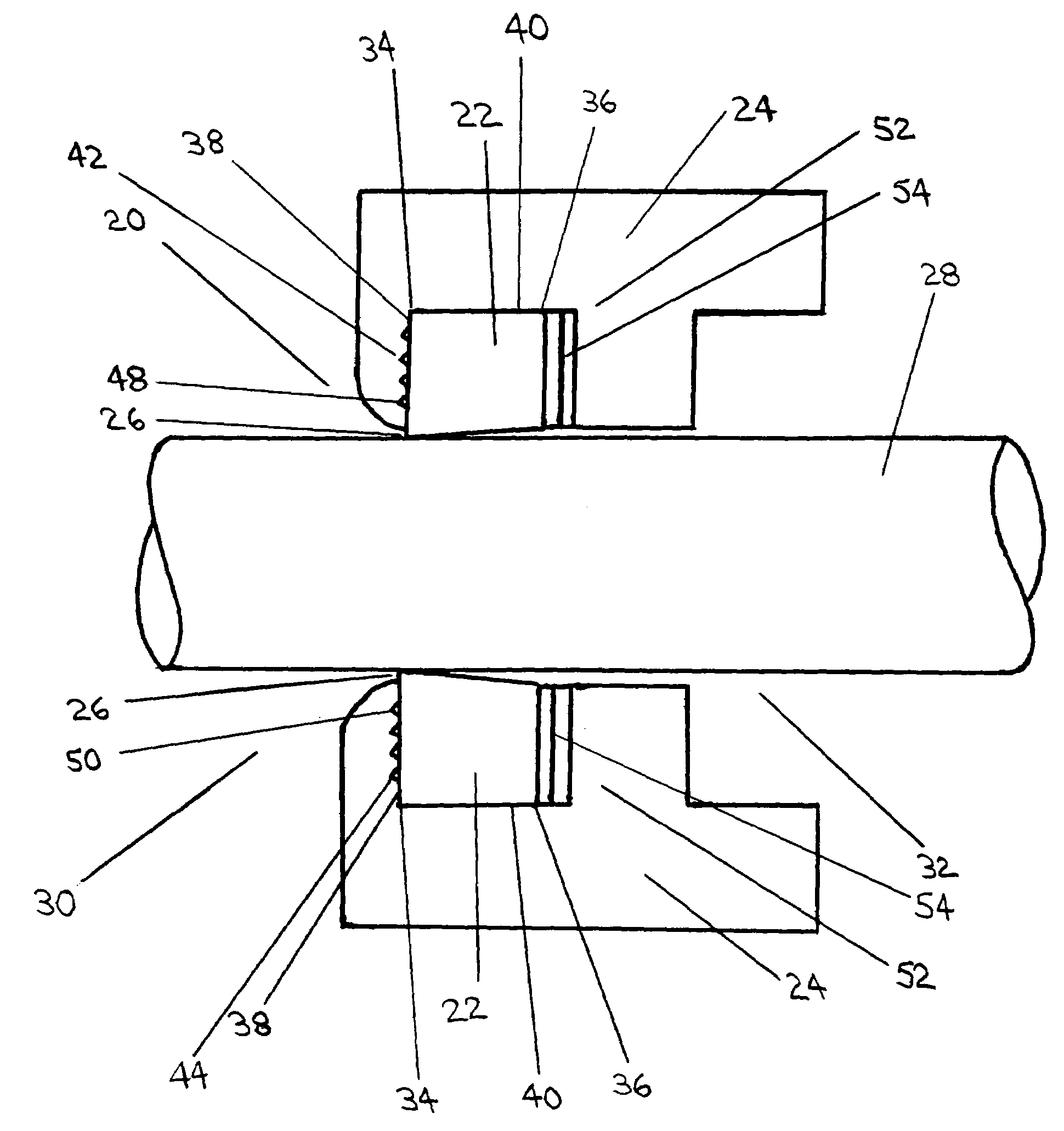
[0032]Referring to FIG. 1, there is depicted a seal assembly (20). The seal assembly (20) includes a seal element (22) and a seal housing (24).

[0033]In the preferred embodiment the seal assembly (20) is a dynamic seal which seals between a sealing surface (26) on the seal element (22) and a rotatable shaft (28) which passes through the seal assembly (20). The seal assembly (20) may, however, be a dynamic seal which seals between the sealing surface (26) and a component which moves longitudinally relative to the seal element (22). The seal assembly (20) may also be a static seal which seals between the sealing surface (26) and a component that does not move relative to the sealing element (22). The seal assembly (20) may therefore be used in a wide range of applications requiring either static or dynamic seals.

[0034]In the preferred embodiment the seal assembly (20) is incorporated into an apparatus (not shown) which supports and contains the rotatable shaft (28). The function of the...


PUM


Abstract

An improvement in a seal assembly for sealing with a rotatable component extending within the seal assembly and defining a longitudinal axis of rotation, the seal assembly being of a type including a seal element retained by a seal housing, where one of the seal element and the seal housing is constructed from a compressible material, where the seal element includes a seal engagement surface and where the seal housing includes a housing engagement surface. The improvement includes one of the seal engagement surface and the housing engagement surface being comprised of the compressible material and the other being oriented in a plane normal to the longitudinal axis of rotation of the component extending within the seal assembly and defining a depression for providing an isolated gap between the seal engagement surface and the housing engagement surface for receiving the compressible material to restrain movement of the seal element relative to the seal housing.

Description

TECHNICAL FIELD[0001]A seal assembly for limiting the amount of movement or distortion experienced by a seal element which is retained by a seal housing.BACKGROUND OF THE INVENTION[0002]In a typical seal assembly a seal element is retained by a seal housing. The seal element provides a sealing surface which in service may be exposed to a variety of forces acting on the seal which tend to move or distort the seal element. This movement or distortion may result in the seal failing to perform as intended either by permitting leakage across the seal or by allowing abrasive media to become embedded in the sealing surface, thus causing premature wearing of the seal element.[0003]The forces acting on the seal may be caused by a pressure differential across the seal element, in which case the sealing surface will tend to move or distort laterally within the seal housing either so that the, sealing force exerted by the sealing surface against its abutting component is reduced or so that the ...

Claims


Application Information

Patent Timeline
Patent Type & Authority Patents(United States)
IPC IPC(8): F16J15/34F16J15/02F16J15/06F16J15/16F16J15/32
CPCF16J15/062F16J15/064F16J15/164F16J15/322
Inventor CARGILL, EDWARD JAMES
Owner HALLIBURTON ENERGY SERVICES INC
Why Eureka
Try Eureka