Multi-variable model for identifying crop response zones in a field

a multi-variable model and crop technology, applied in image enhancement, image analysis, instruments, etc., can solve the problems of few reliable conclusions that can be drawn for a grower, ineffective control of conditions, and inability to know the successful methodology that has been developed for taking data

Inactive Publication Date: 2006-06-06
THE BOARD OF TRUSTEES OF THE UNIV OF ILLINOIS
View PDF54 Cites 201 Cited by
  • Summary
  • Abstract
  • Description
  • Claims
  • Application Information

AI Technical Summary

Benefits of technology

[0001]Remote sensing is the science of acquiring information about the earth's land and water resources without coming into physical contact with the feature to be studied. One of three basic outcomes can effect light (electromagnetic energy) as it passes through the earth's atmosphere and strikes an object; it can be absorbed, reflected or transmitted. In general, r

Problems solved by technology

While there have been various prior art attempts to eliminate these kinds of unwanted variation, (i.e., using laser light sources at night instead of the sun as a light source, schemes for adjusting the variation in photographic film, and others) the inventors are not aware of successful methodology that has been developed for taking the data as collected and then satisfactorily adjusting the data itself for comparison over time (i.e., through a growing season).
As reliable data comparisons have not been made in the prior art, there are few reliable conclusions that can be drawn for a grower to help him in making the few decisions that are within his power to decide.
This powerfully eliminates the effects of varying influences by factoring them out of the data while the prior art has either rather ineffectively sought to

Method used


Image

  • Multi-variable model for identifying crop response zones in a field
  • Multi-variable model for identifying crop response zones in a field
  • Multi-variable model for identifying crop response zones in a field

Examples


Embodiment Construction

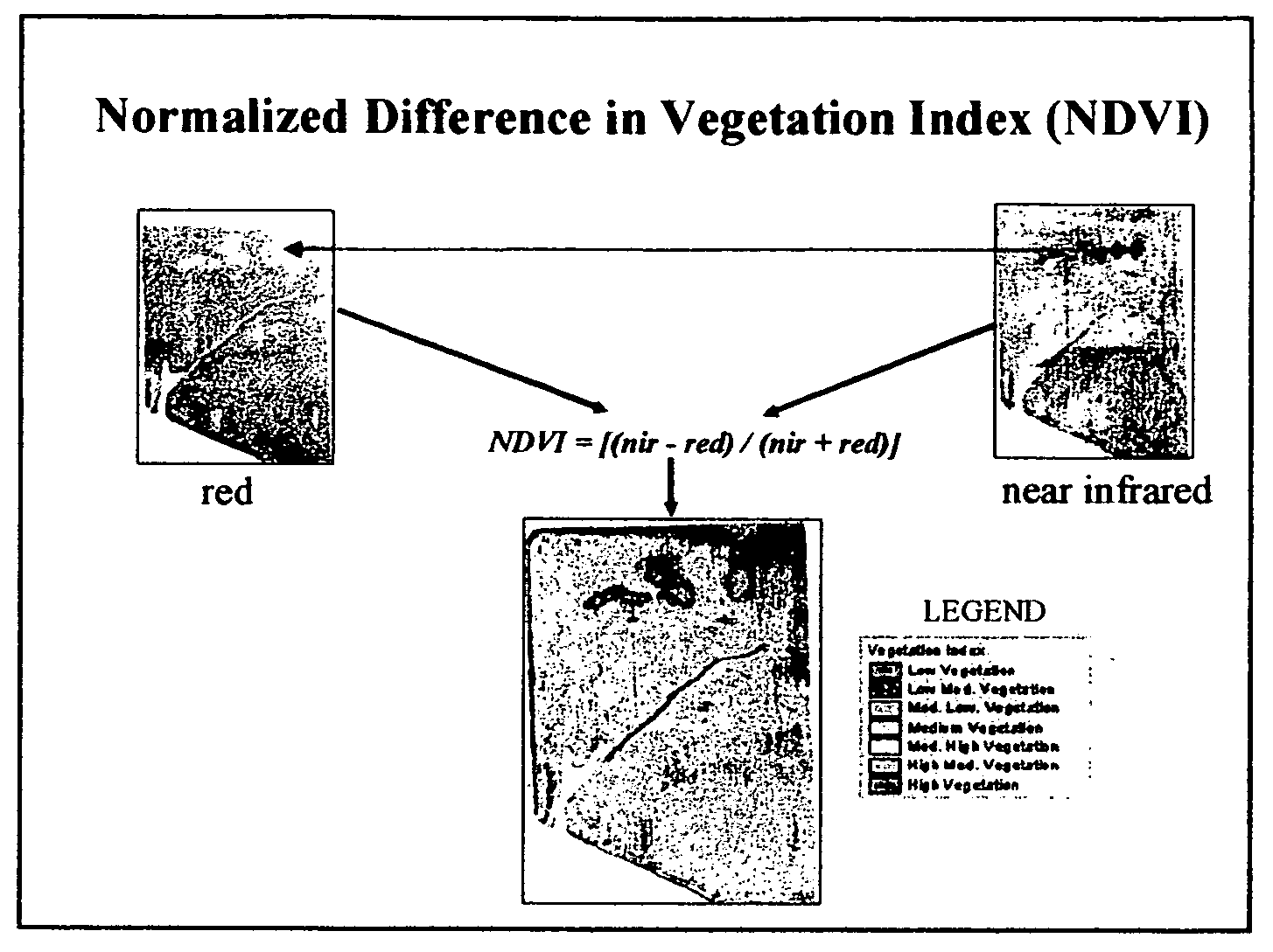
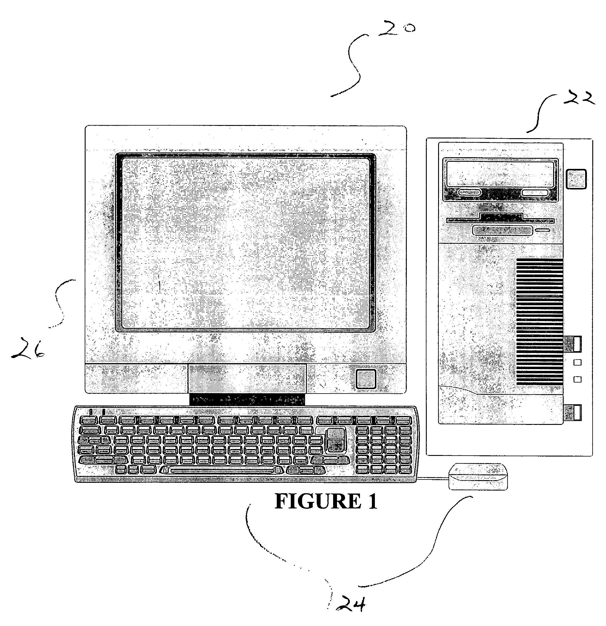
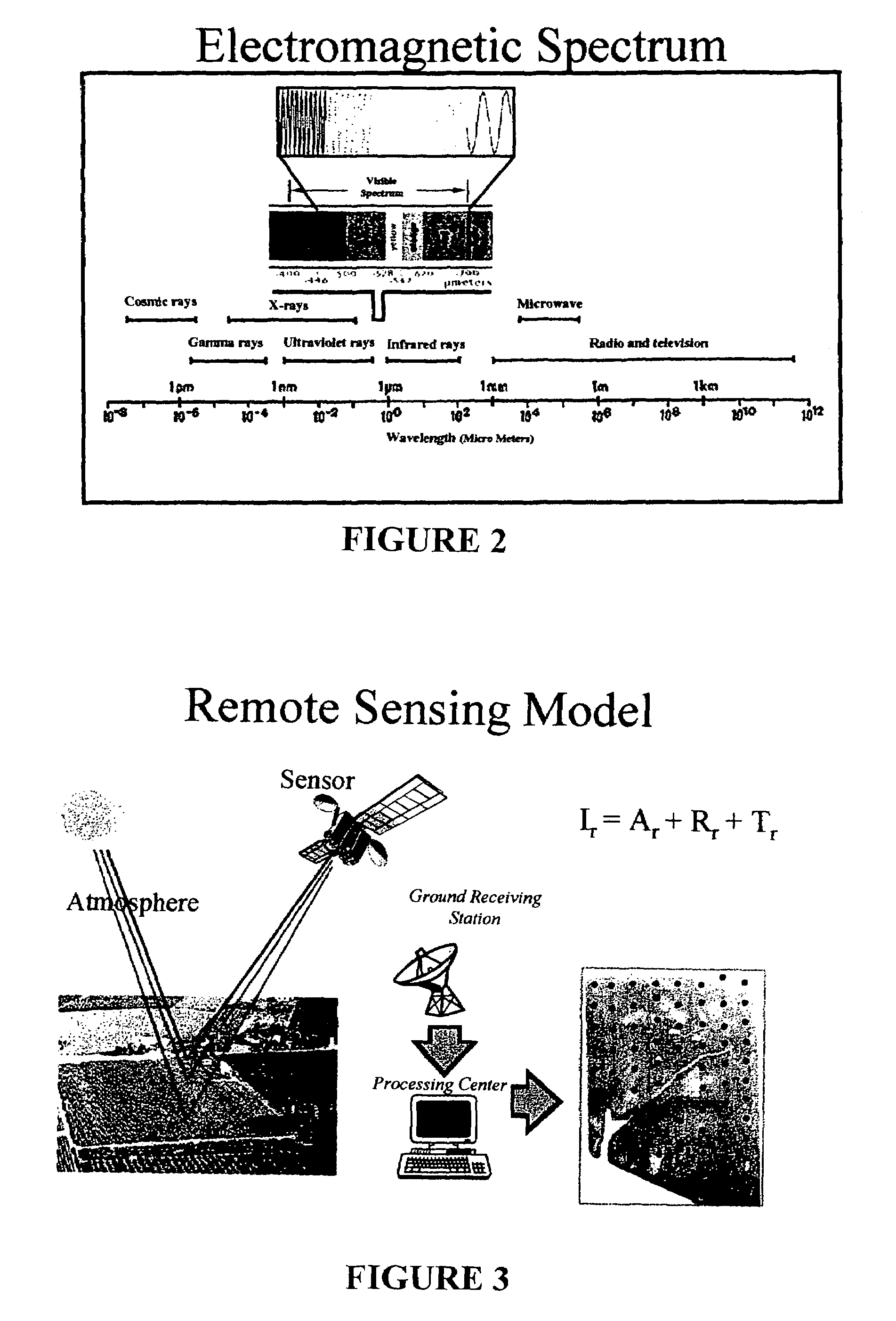
[0030]The present invention takes advantage of the remote sensing of visible and infrared radiation reflected from crops in order to generate the initial raw data. This raw data is then converted to a vegetation index value. The converted data is then aggregated, clustered, and classified into crop response zones. The process and methodology of creating crop response zones may by readily achieved by processing data on a personal computer, preferably a more powerful pc such as a workstation. As shown in FIG. 1, a personal computer 20 has a processor 22, a variety of input devices 24 such as a keyboard, mouse, etc. as is well known in the art, and a display 26 which preferably is a larger size such as 22′ computer monitor capable of producing color images. The majority of the computer programs used in the present invention are commercially available, except for the normalization step which is performed by the particular software program mentioned and included in this disclosure. This ...


PUM


Abstract

An computer implemented apparatus and method are disclosed for defining areas of a field in which a crop or other vegetation is grown based on their selective ability to grow such vegetation through a growing season, or some shorter preselected time period. The method includes making a number of temporally separated measurements through air borne imaging of a field, registering the data to the geography of the field and each other, normalizing the data including converting the data to a vegetative index indicative to the presence of vegetation in the field, comparing the data to identify clusters of like value, and classifying the clusters and images to learn how the different field areas responded in growing vegetation through the season. With this method, the field may be segregated into a number of like areas called crop response zones which exhibit similar vegetative growth characteristics as an aid to a grower in his decision making regarding how to maximize yield in his field.

Description

BACKGROUND AND SUMMARY OF THE INVENTION[0001]Remote sensing is the science of acquiring information about the earth's land and water resources without coming into physical contact with the feature to be studied. One of three basic outcomes can effect light (electromagnetic energy) as it passes through the earth's atmosphere and strikes an object; it can be absorbed, reflected or transmitted. In general, remote sensing measures that part of the electromagnetic spectrum that is either reflected or emitted (thermal energy) from an object. As an object (green plant) grows, generally, the leaf area of the plant increases, and the different portions of the electromagnetic spectrum respond accordingly (i.e., red reflectance decreases and near-infrared reflectance increases).[0002]There are different methods of data collection from remote sensing systems; a single band (panchromatic), several bands (multi spectral) or hundreds of bands (hyperspectral). These images of reflectance can be use...

Claims


Application Information

Patent Timeline
IPC IPC(8): G06K9/00G06T5/00G06T7/40
CPCG06K9/00657G06T7/0081G06T7/402G06T2207/30188G06T2207/10032G06T2207/20064G06T7/11G06T7/42G06V20/188
Inventor MCGUIRE, JOHN DENNISPEARSON, RANDALL SCOTT
Owner THE BOARD OF TRUSTEES OF THE UNIV OF ILLINOIS
Why Eureka
Try Eureka