Object location monitoring within buildings

a technology for object location and monitoring, applied in the direction of instruments, navigation instruments, electric signalling details, etc., can solve the problems of high degree of synchronization between the receivers, system implementation is difficult and expensive, and the location monitoring is not well suited to the object, so as to reduce the ambiguity and the effect of signal blockag

Inactive Publication Date: 2006-05-02
GE MEDICAL SYST INFORMATION TECH
View PDF26 Cites 201 Cited by
  • Summary
  • Abstract
  • Description
  • Claims
  • Application Information

AI Technical Summary

Benefits of technology

[0005]In a preferred embodiment, chirpers or “beacons” that intermittently transmit unique ID codes are mounted to walls or other structures throughout areas of a building. The beacons are preferably maintained in coarse synchronization such that nearby beacons do not transmit simultaneously. In accordance with one aspect of the invention, the beacons are synchronized using the 60 Hz cycle of a standard 120V AC (alternating current) power signal within the building—either by monitoring the power signal directly or by monitoring the flicker of the lighting within the building. Two or more beacons are preferably provided in different locations within each room to reduce ambiguities and the effects of signal blockage.

Problems solved by technology

One problem with this approach is that it is not well suited for monitoring the locations of objects within a building having multiple rooms.
A significant problem with this approach is that a high degree of synchronization is required between the receivers to produce accurate results.
As a result, such a system tends to be difficult and expensive to implement.

Method used


Image

  • Object location monitoring within buildings
  • Object location monitoring within buildings
  • Object location monitoring within buildings

Examples


Embodiment Construction

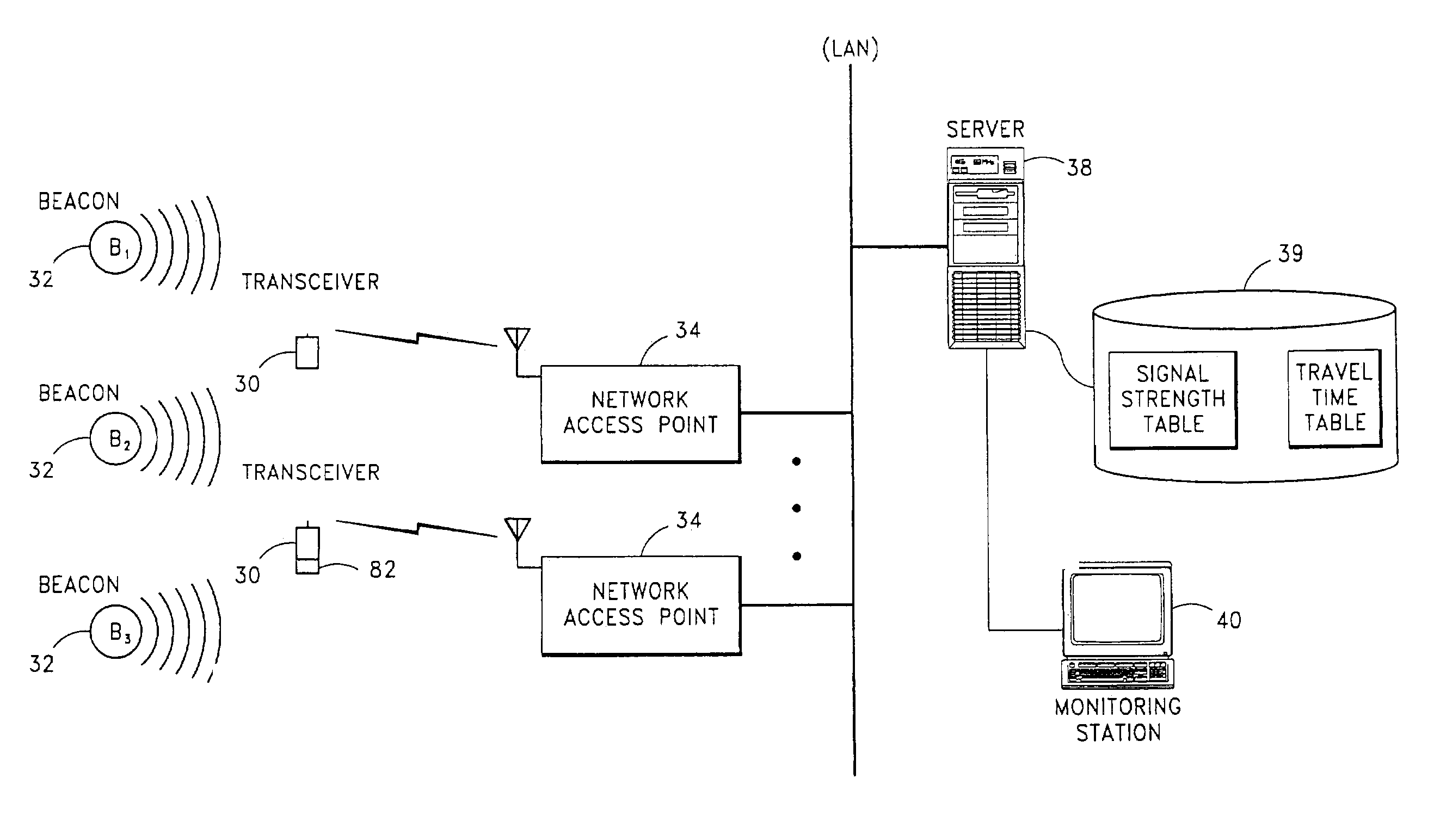
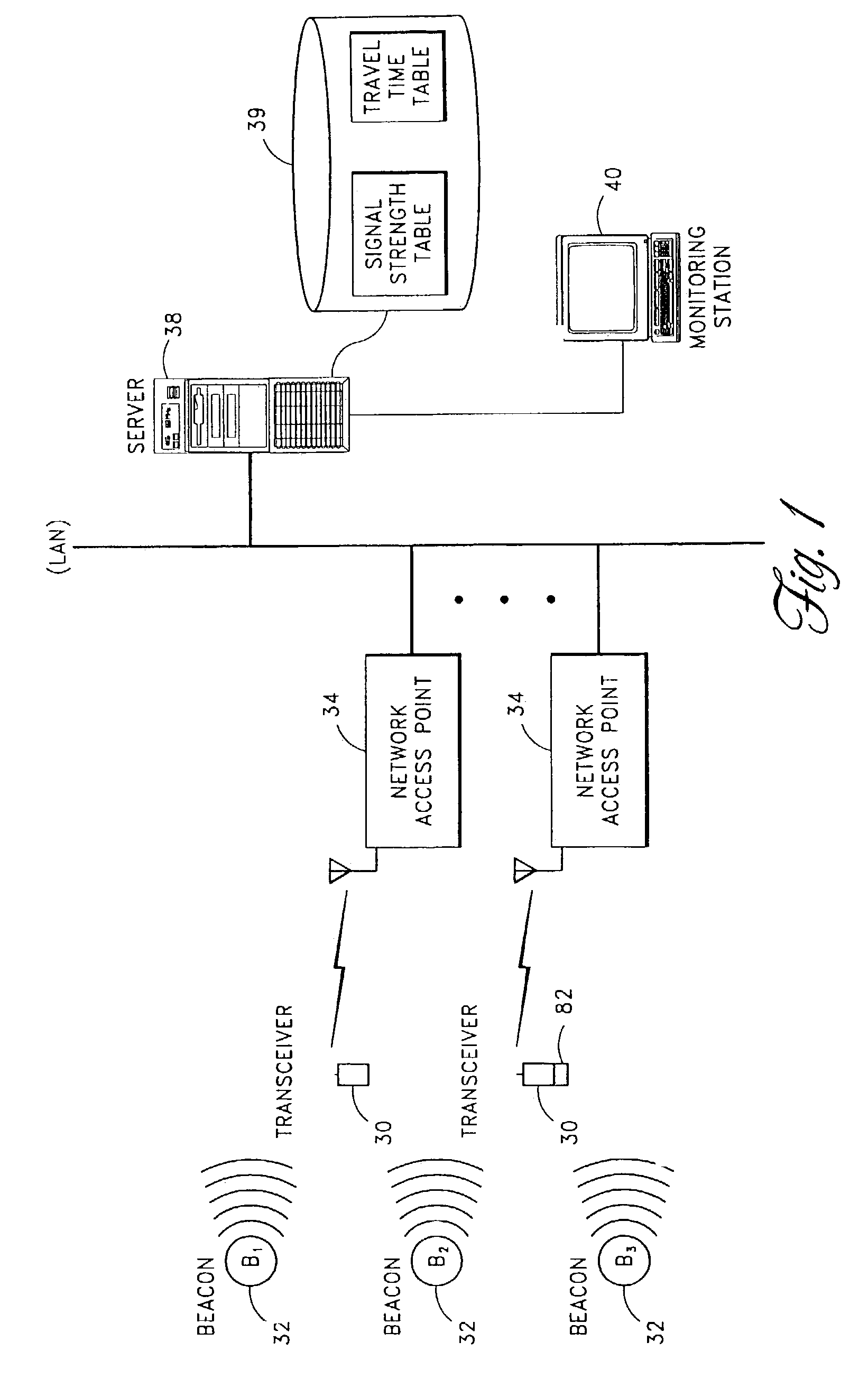
[0022]The structure and operation of a system in accordance with the present invention are illustrated below. In the particular embodiment illustrated, the preexisting infrastructure of a medical telemetry system (remote patient transceivers, access points, LAN, etc.) are used to monitor locations of patients within a medical facility. As will be apparent, the invention may also be implemented using other types of preexisting infrastructure, such as the general-purpose wireless LAN infrastructure of a building (e.g., to track laptop computers and other wireless computing devices). In addition, the invention may be implemented using special purpose transceivers and other components designed specifically for object location monitoring. Thus, the description of this particular embodiment is intended to illustrate, and not limit, the scope of the present invention.

[0023]FIG. 1 illustrates the components of a medical telemetry system that embodies the present invention. The medical telem...


PUM


Abstract

An object location tracking system for tracking a movable object includes a plurality of beacons spatially distributed within a building, each beacon transmitting a respective ID signal, at least one transceiver device which receives the transmission of ID signals from the beacons and determines received signal strengths of such transmissions, the transceiver device adapted to be attached to the movable object, a motion detector coupled to the at least one transceiver device configured to provide information relating to a motion of the at least one transceiver device, and a processing module that uses information reflective of the received signal strengths of the transmissions received by the transceiver device, in combination with information reflective of the motion of the at least one transceiver device, to determine a current location of the transceiver device.

Description

CROSS-REFERENCE TO RELATED PATENT APPLICATIONS[0001]This is a continuation-in-part of application Ser. No. 09 / 882,122, filed Mar. 30, 2001 now U.S. Pat. No. 6,529,164 (incorporated by reference herein) which claims the benefit of U.S. Provisional Application No. 60 / 193,655, filed Mar. 31, 2000 (incorporated by reference herein).BACKGROUND OF THE INVENTION[0002]Various approaches have been proposed for monitoring the locations of objects within an area. One such approach uses radio frequency (RF) transmitters or tags, attached to the objects to be tracked, and an array of receivers for receiving tag transmissions throughout a tracking area. The signal strengths of the received tag transmissions may then be used to determine a tag's distance from the receivers. One problem with this approach is that it is not well suited for monitoring the locations of objects within a building having multiple rooms. In such an environment, the unpredictable attenuation of transmissions passing throug...

Claims


Application Information

Patent Timeline
Patent Type & Authority Patents(United States)
IPC IPC(8): G08B1/08G01S5/00G01S5/02G01S19/05G01S19/11
CPCG01S5/0036G01S5/02G01S5/0252G01S5/0205G01S2205/002G01S2205/02
Inventor CARTER, SCOTT J.
Owner GE MEDICAL SYST INFORMATION TECH
Why Eureka
Try Eureka