Pressure limiting device for a hydraulic braking circuit of vehicle

Active Publication Date: 2010-01-26
BERINGER
View PDF16 Cites 0 Cited by
  • Summary
  • Abstract
  • Description
  • Claims
  • Application Information

AI Technical Summary

Benefits of technology

[0012]To solve the problem tackled of allowing the free flow of hydraulic fluid resulting from the rise in pressure and then, as from the set pressure, allowing reduction of this pressure in the braking components of the back wheel or wheels, the arrangements in the body consist of a coaxial bore that opens out of one of the piston heads on the side where the hydraulic circuit of the braking components of the back wheel or wheels is connected, the said bore, which communicates with the fluid coming from the braking components of the front wheel or wheels, being fitted with a ball controlled by a spring that co-operates with a coaxial finger of a leaktight closure component fitted in the bore in the housing such that, depending on the set pressure, the fluid can flow freely or the entire body-piston assembly can move.

Problems solved by technology

It is also known that the act of braking, which consists of a deceleration, causes the transfer of mass to the front of the vehicle such that there tends to be loss of weight at the rear of the vehicle that is capable of causing breakaway such as that found in motorcycles.
In actual fact, when the user uses the actuating components there is a rise in pressure that results in the theoretical curve being exceeded, resulting in one or more of the back wheels locking.
Moreover, such limiters are sensitive to the speed at which pressure rises.

Method used


Image

  • Pressure limiting device for a hydraulic braking circuit of vehicle
  • Pressure limiting device for a hydraulic braking circuit of vehicle
  • Pressure limiting device for a hydraulic braking circuit of vehicle

Examples


Embodiment Construction

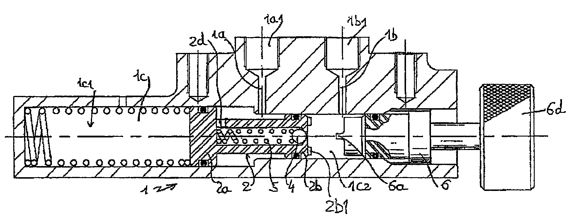
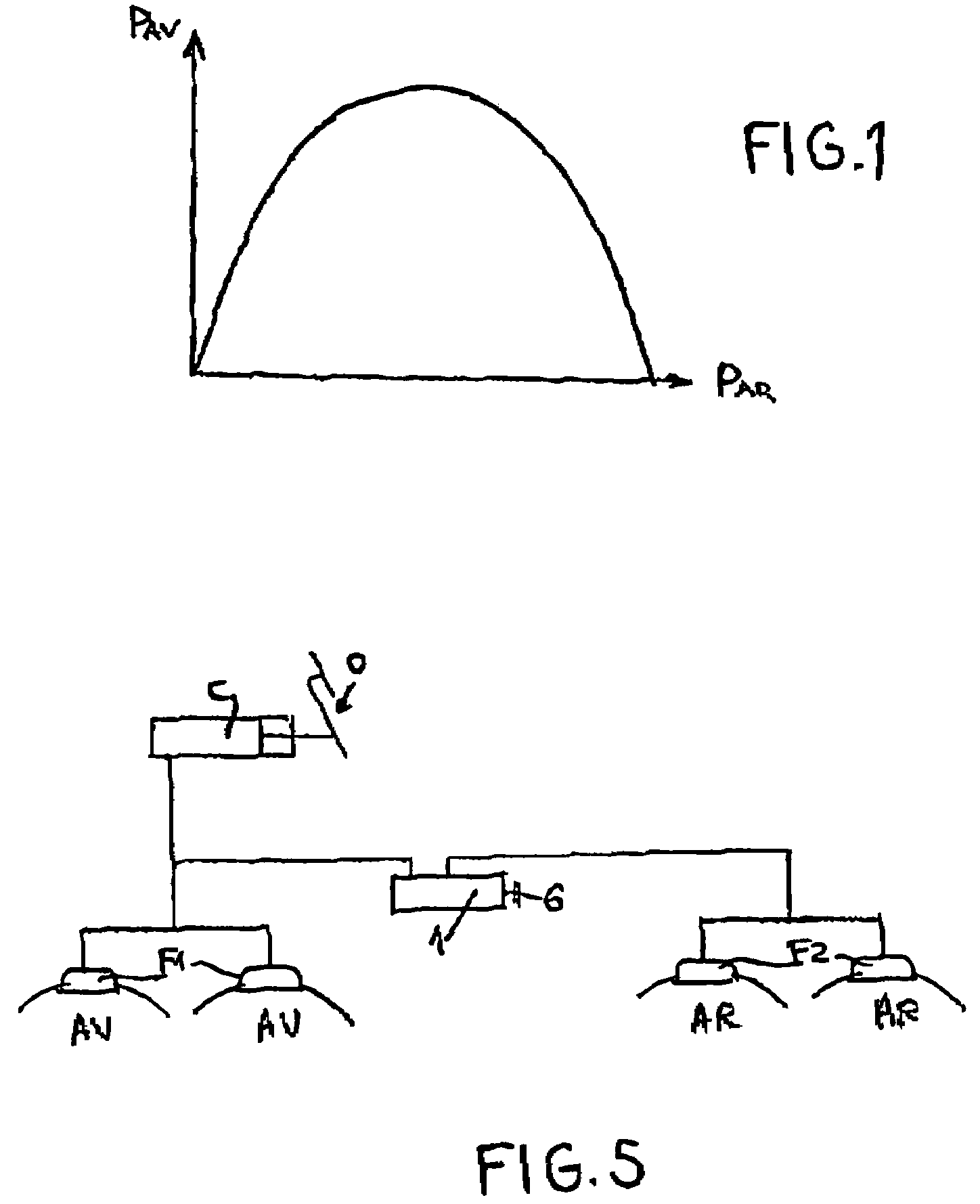
[0027]The pressure limiting device of the invention comprises a small leaktight housing (1) capable of being included or added to a hydraulic circuit designed to control braking components. As seen in FIG. 5, the pressure limiter is hydraulically connected between the braking components (F1) of the front wheel or wheels (AV) and the braking components (F2) of the back wheel or wheels (AR). In standard ways that are well known to those skilled in the art, the braking components (F1) and (F2) are controlled by a master cylinder (C) that is controlled by the actuating component (O) that may be a pedal, handle or other depending on the type of vehicle to be equipped.

[0028]The housing (1) constitutes a compact, independent assembly that is shaped roughly like a rectangular box. The walls of the housing (1) contain channels (1a) and (1b) that communicate with a connection bearing (1a1), (1b1) to connect up with the hydraulic braking circuit. This connection can, for example, be achieved b...


PUM


Abstract

The device comprises a leaktight housing which is hydraulically connected between braking elements of the front and rear wheel(s). The housing comprises a body and fittings which enable the hydraulic fluid to flow into the braking elements of the rear wheels until an adjustable set pressure is obtained, after which the pressure is reduced in the braking elements of the rear wheel(s) in a manner which is proportional to the pressure increase in the braking elements of the front wheel(s).

Description

CROSS-REFERENCE TO RELATED APPLICATIONS[0001]This application is a 35 U.S.C. 371 filing of International Application PCT / FR2004 / 050538 filed on Oct. 27, 2004 and published, in French, as International Publication WO 2005 / 042324 A2 on May 12, 2005, which claims priority from French application no. 0312952 filed on Oct. 29, 2003, which applications are incorporated herein by reference in their entirety.BACKGROUND OF THE INVENTION[0002]The invention relates to the sector of braking control circuits for all types of vehicle, particularly automobiles and motorcycles.[0003]As stated, the invention has particularly advantageous applications in the hydraulic braking circuits of vehicles where force must be applied to an actuating component such as a handle or pedal to deliver pressure capable of acting on the braking components. This type of application must not, however, be considered as strictly limitative.[0004]It is known by those skilled in the art that braking components, particularly...

Claims


Application Information

Patent Timeline
IPC IPC(8): B60T13/00B60T8/26B60T11/34
CPCB60T8/265B60T11/34
Inventor BERINGER, GILBERT
Owner BERINGER
Why Eureka
Try Eureka