
Pin grid array socket having a base with interior standoffs and hightening peripheral walls

a grid array socket and pin technology, applied in the field of electric socket connectors, can solve the problems of pin interference with the cavity walls, and it is difficult to achieve a socket connector with high-density contacts restrained

Inactive Publication Date: 2010-01-26
HON HAI PRECISION IND CO LTD
View PDF3 Cites 6 Cited by
  • Summary
  • Abstract
  • Description
  • Claims
  • Application Information

AI Technical Summary

Benefits of technology

[0009]An object of the present invention is to provide a socket connector with resilient contact portions over the upper surface of apertures in an insulateive base able to effective prevent contacts and pins from deformation resulted from a sunk cover during the period of mounting a CPU or taking by a user.

Problems solved by technology

As the sharply growing numbers of pins of an CPU and corresponding passageways in which contacts secure, there is a possibility that the lead pins will interfere with the cavity walls during insertion and horizontal movement of the lead pins.
Accordingly it is difficult to achieve a socket connector with high-density contacts restrained in narrow pitches due to these dimensional constraints.

Method used


Image

  • Pin grid array socket having a base with interior standoffs and hightening peripheral walls
  • Pin grid array socket having a base with interior standoffs and hightening peripheral walls
  • Pin grid array socket having a base with interior standoffs and hightening peripheral walls

Examples


Embodiment Construction

[0020]While the invention may be susceptible to embodiment in different forms, there is shown in the drawings, and herein will be described in detail, a specific embodiment with the understanding that the present disclosure is to be considered an exemplification of the principles of the invention, and is not intended to limit the invention to that as illustrated and described herein.

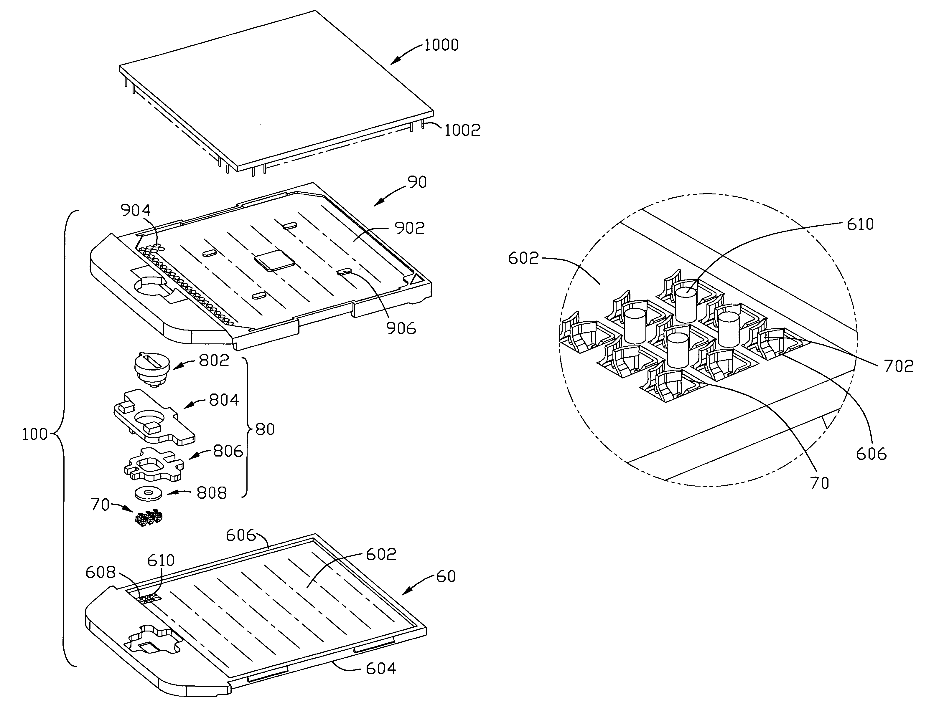
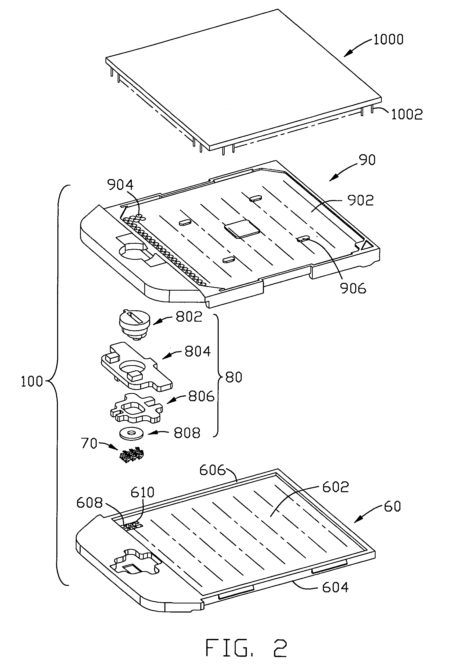
[0021]The preferred embodiment of the PGA Type socket connector (hereinafter, referred to as “socket connector”) of the present invention will describe in detail with reference to the attached drawing. Referring to FIGS. 2-6, the major component of the socket connector includes a base 60, a plural of contacts 70, a screw cam 80, and a cover 90. The base 60 has a top surface 602 and mounting surface 604 and a plurality of opposing peripheral walls 606 extending upward from the sides of the base 60 to define a cavity. The cavity comprising an interior area having a plural of passageways 608 in which a plur...


PUM

PropertyMeasurementUnit
specific heightaaaaaaaaaa
areaaaaaaaaaaa
right-angleaaaaaaaaaa

Abstract

A socket connector is provided for securely mounting an electronic device (1000) on a printed circuit board, said socket connector comprises an insulatve base (60) and heightened perimeter walls (606) upward extending therefrom to define an inner cavity. The top surface (602) of the inner cavity comprises a plural of passageways (608) in which a plural of contacts (70) hold. Furthermore, there are a plural of standoffs (610) between the adjacent passageways (608) co-worked with the heightened perimeter walls (606) for effectively preventing a cover (90) from deformation.

Description

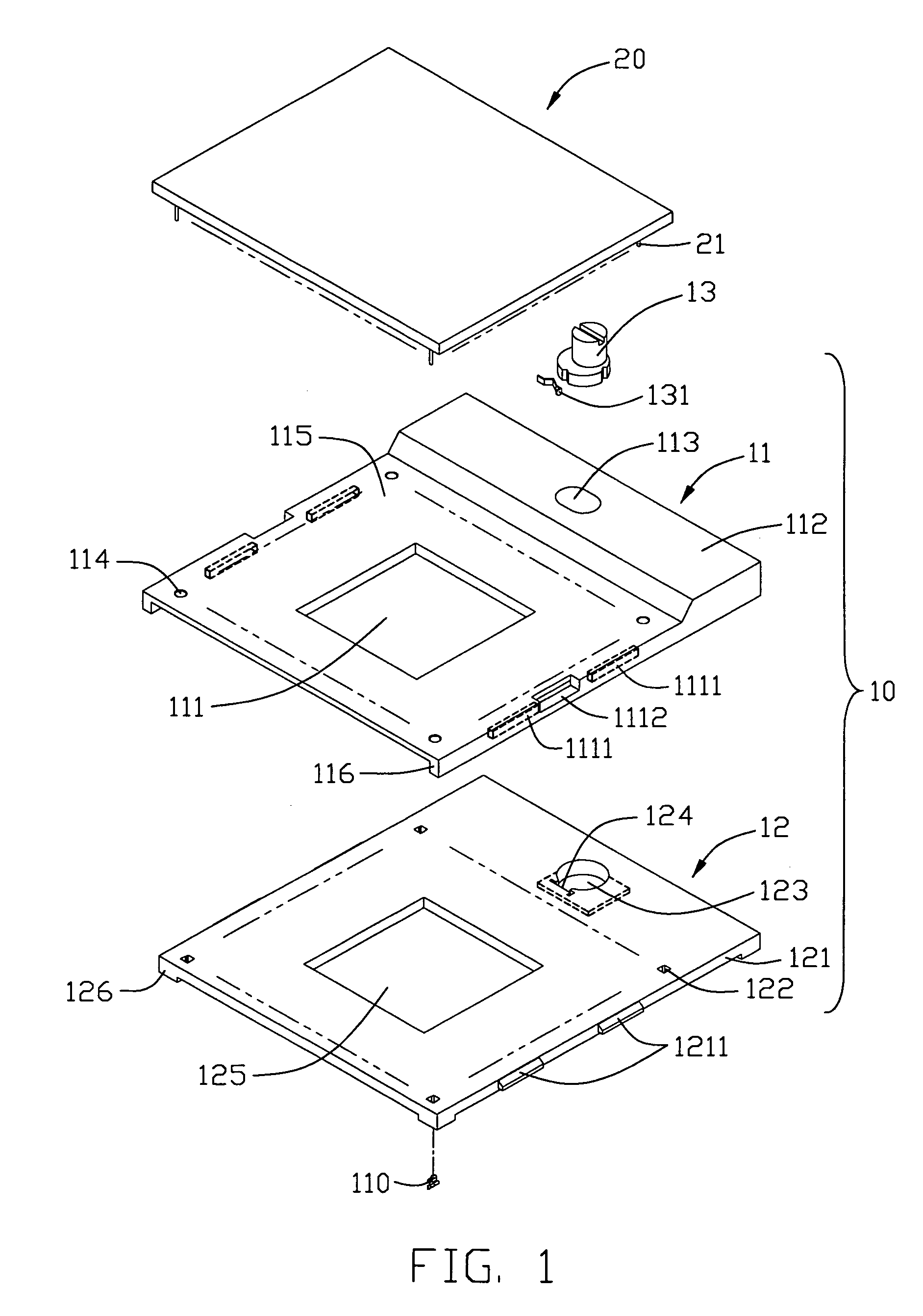
BACKGROUND OF THE INVENTION[0001]1. Field of the Invention[0002]The present invention generally relates to an electrical socket connector, and more particularly to a Pin Grid Array (PGA) socket having a base with a plurality of standoffs extending upward from a top surface thereof so as to provide addition space for contact engaging arms of contact terminals assembled therein.[0003]2. Description of Related Art[0004]U.S. Pat. No. 6,340,309 issued to Lin on Jan. 22, 2002, as shown in FIG. 1, discloses a pin grid array (PGA) socket 10 on which a CPU 20 is mounted. The CPU 20 has a plurality of pins 21 extending through a cover 11 into a dielectric base 12 of the socket for electrically engaging with contacts 110 received in the base. The cover 11 of the PGA socket 10 comprises a main body 115 and a raised portion 112 in front of the main body 115. The raised portion 112 defines an elliptic aperture 113 in middle thereof. Two opposite side walls 116 of the cover 11 are extended downwar...

Claims


Application Information

Patent Timeline
Patent Type & Authority Patents(United States)
IPC IPC(8): H01R43/00H01R12/71
CPCH05K7/1084Y10T29/49124
Inventor LIAO, FANG-CHU
Owner HON HAI PRECISION IND CO LTD
Learn More