Ultrasound communication system for metal structure and related methods

a communication system and metal structure technology, applied in the field of ultrasonic communication systems for metal structures, can solve the problems of increasing the cost of retrofitting a sensor network such as in the aircraft fleet, reducing the reliability of the structure, so as to reduce interference, improve the communication range, and simplify the transmission system

Active Publication Date: 2010-02-02
LOCKHEED MARTIN CORP
View PDF6 Cites 28 Cited by
  • Summary
  • Abstract
  • Description
  • Claims
  • Application Information

AI Technical Summary

Benefits of technology

[0007]In view of the foregoing, embodiments of the present invention provide a system having a real-time sensor network capable of being effectively embedded in a structure such as an airframe to provide measurements to a central location. For example, data communication for an embodiment of a system having this sensor network can be wireless so that thin sensors can be easily embedded into the skin of a wing or airframe without the need to wire the sensors for power or communication. By providing embodiments of systems and methods of the present inventions which include wireless communication, the wireless communication of sensor information can reduce the installation costs of sensor networks. By utilizing the benefits of ultrasound communication, which is also wireless, problems often associated with RF communications can be eliminated.
[0009]In embodiments of systems and methods of the present invention, for example, ultrasound transducers can be attached to metal or composite structures, including airframes, shipping containers, pipes and bridges, and used to communicate sensor information to an ultrasound receiver through the structure. Also, the ultrasound transducers coupled to the metal or composite structure can be modulated to produce Lamb waves that travel to the ultrasound receiver. The ultrasound transmitters can use frequency-hopped signals to digitally encode transducer information among different transmitters. The transmitters are operated asynchronously. The ultrasound receiver for example, can use a channel equalizer to reduce the effects of signal multipath and decode the transducer information from the ultrasound transmitters.
[0010]An embodiment of a system according to the present invention includes a structure, a plurality of ultrasound transmitters each connected to and spaced-apart along the structure to transmit modulated ultrasound communication along the structure, and an ultrasound receiver positioned remote from the plurality of ultrasound transmitters and connected to the structure to receive the modulated ultrasound communication from each of the plurality of ultrasound transmitters. The plurality of ultrasound transmitters can be networked and in communication with a modulator to modulate each of the plurality of ultrasound transmitters. The ultrasound receiver, in turn, can include a decoder to decode the modulated ultrasound communication and a channel equalizer to reduce the effects of signal multipath.
[0012]Beneficially, for example, ultrasound frequencies can be selected so that they are non-dispersive based on Lamb wave propagation characteristics of the metal or composite structure. Because each of the transmitters in embodiments of the systems and methods of the present inventions are transmit only, they do not require a receiver with which to become synchronized. Therefore, the transmitters can be significantly simplified as compared to other known transmitters in this field. An array of transducers can also be used at the receiver. This offers the possibility of increased communication range and / or reduced interference, and / or reduced multipath. In both cases, transducer arrays can allow more possibilities for locating sensors and network layout. In some instances, outbound messages may be destined for a receiver that is beyond reach. In this case, the use of intermediate nodes to relay data can be used. One example is a dummy node which simply amplifies received signals. A second example is demodulation to an alternate frequency. A third example is decoding and retransmission.

Problems solved by technology

Wiring, for example, can further degrade the integrity of the structure, especially for composites, and can increase the cost of retrofitting a sensor network such as in an aircraft fleet.
In addition, RF solutions can be high power, requiring relatively large battery sources for the embedded sensors.
Wireless communication via RF can produce unwanted RF signatures and interference in some applications as well.
RF communication may also be impractical in some applications due to excessive multipath or RF interference.

Method used


Image

  • Ultrasound communication system for metal structure and related methods
  • Ultrasound communication system for metal structure and related methods
  • Ultrasound communication system for metal structure and related methods

Examples


Embodiment Construction

[0055]The present invention now will be described more fully hereinafter with reference to the accompanying drawings in which embodiments of the invention are shown. This invention may, however, be embodied in many different forms and should not be construed as limited to the embodiments set forth herein; rather, these embodiments are provided so that this disclosure will be thorough and complete, and will fully convey the scope of the invention to those skilled in the art. Like numbers refer to like elements throughout.

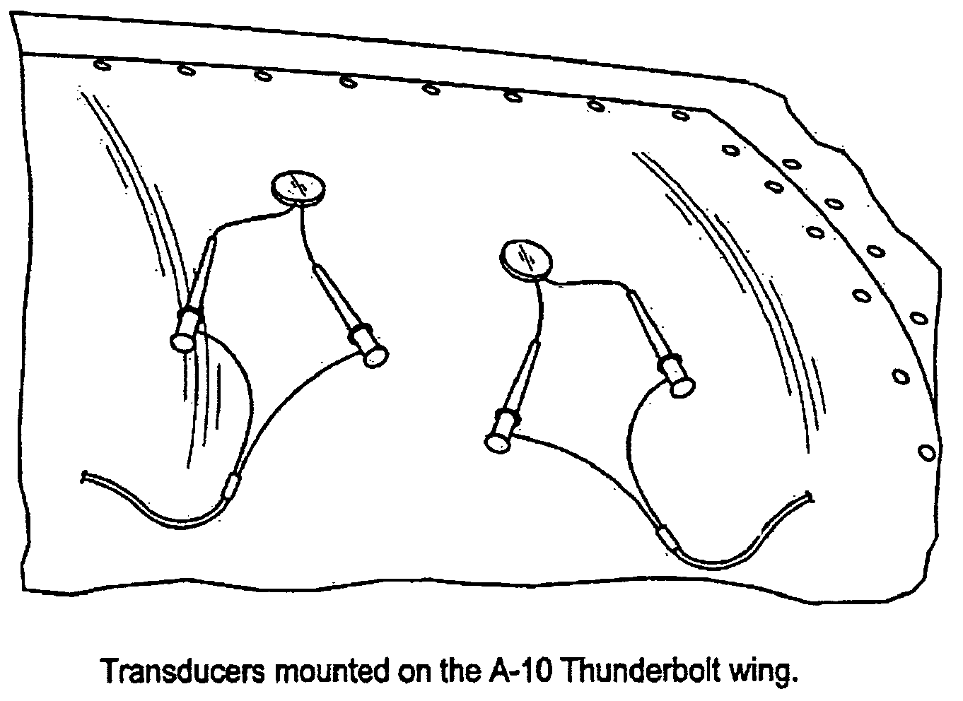
[0056]As illustrated in FIGS. 1-40, and as described herein, embodiments of systems and methods of the present invention can be applicable to an airplane structure or a shipping container, for example. As understood by those skilled in the art, however, the present invention is also applicable to piping, bridges, and other structures as well. Ultrasound communication in an airframe for example, requires the efficient propagation of ultrasound energy in metal structur...


PUM

PropertyMeasurementUnit
frequencyaaaaaaaaaa
frequencyaaaaaaaaaa
acoustic frequencyaaaaaaaaaa

Abstract

Embodiments of the present invention beneficially provide an ultrasound communication system and methods of ultrasound communication for diagnostics and prognostics of structures. For example, ultrasound transmitters are connected to a metal or composite structure and modulated to produce Lamb waves that travel to an ultrasound receiver. The ultrasound transmitters can use frequency-hopped signals to digitally encode transducer information among different transmitters. The transmitters can be operated asynchronously. The receiver can use a channel equalizer to reduce the effects of signal multipath and a decoder to decode the transducer information from the ultrasound transmitters.

Description

RELATED APPLICATIONS[0001]The present application claims priority to and the benefit of U.S. Provisional Patent Application Ser. No. 60 / 692,744 filed on Jun. 22, 2005 titled “Ultrasound Communication System and Related Methods” and which is incorporated herein by reference in its entirety.BACKGROUND OF THE INVENTION[0002]1. Field of the Invention[0003]The present invention relates to communication to and from structures and, more particularly, to systems and methods for monitoring and communication to and from structures.[0004]2. Description of Related Art[0005]As our military aircraft fleet ages, Applicants recognize that it will become increasing important to provide prognostic health management (PHM) of a structure such as a frame of an aircraft or other type of vehicle. For example, PHM may provide a way to predict when the aircraft structure has degraded to the point where it no longer meets safety margins due to metal fatigue. In newer aircraft made from composite materials, s...

Claims


Application Information

Patent Timeline
Patent Type & Authority Patents(United States)
IPC IPC(8): G01N29/04
CPCG01N29/07G01N29/11G01N2291/0231G01N2291/0422G01N2291/0427G01N2291/102G01N2291/2694
Inventor TOMLINSON, JR., HAROLD W.DEATON, JR., JOHN B.NIETERS, EDWARDROSS, FERGUS
Owner LOCKHEED MARTIN CORP
Why Eureka
Try Eureka