Unlock instant, AI-driven research and patent intelligence for your innovation.

Method of designing a low cost multibeam phased array antenna for communicating with geostationary satellites

a phased array, low-cost technology, applied in the direction of antennas, electrical appliances, radio transmission, etc., can solve the problems of complex array configuration and high cost of antenna implementation, and achieve the effect of reducing array complexity and cos

Inactive Publication Date: 2010-02-02
NAVY USA AS REPRESENTED BY THE SEC OF THE THE
View PDF1 Cites 6 Cited by
  • Summary
  • Abstract
  • Description
  • Claims
  • Application Information

AI Technical Summary

Benefits of technology

[0013]In an embodiment of the invention, a single broadband multibeam planar array in a mobile earth station is used to communicate with several GEO satellites simultaneously by generating multiple beams which need to be scanned only in one plane. Such an embodiment requires only M instead of NM phase shifters for each beam and uses, for example, only one or two fixed (or hard-wired) squints in the orthogonal plane, depending on the application requirements. This approach significantly reduces array complexity and cost as compared to the conventional NM phase shifters approach.

Problems solved by technology

However, it is very expensive to implement this antenna because NM (N×M) phase shifters are needed for each beam to scan in the two planes.
However, achieving variable squints is akin to having a limited scan capability, which still calls for a new phase adjustment at each element whenever a mobile earth station's (e.g., ship's) location changes.
This still requires a complicated array configuration.

Method used


Image

  • Method of designing a low cost multibeam phased array antenna for communicating with geostationary satellites
  • Method of designing a low cost multibeam phased array antenna for communicating with geostationary satellites
  • Method of designing a low cost multibeam phased array antenna for communicating with geostationary satellites

Examples


Embodiment Construction

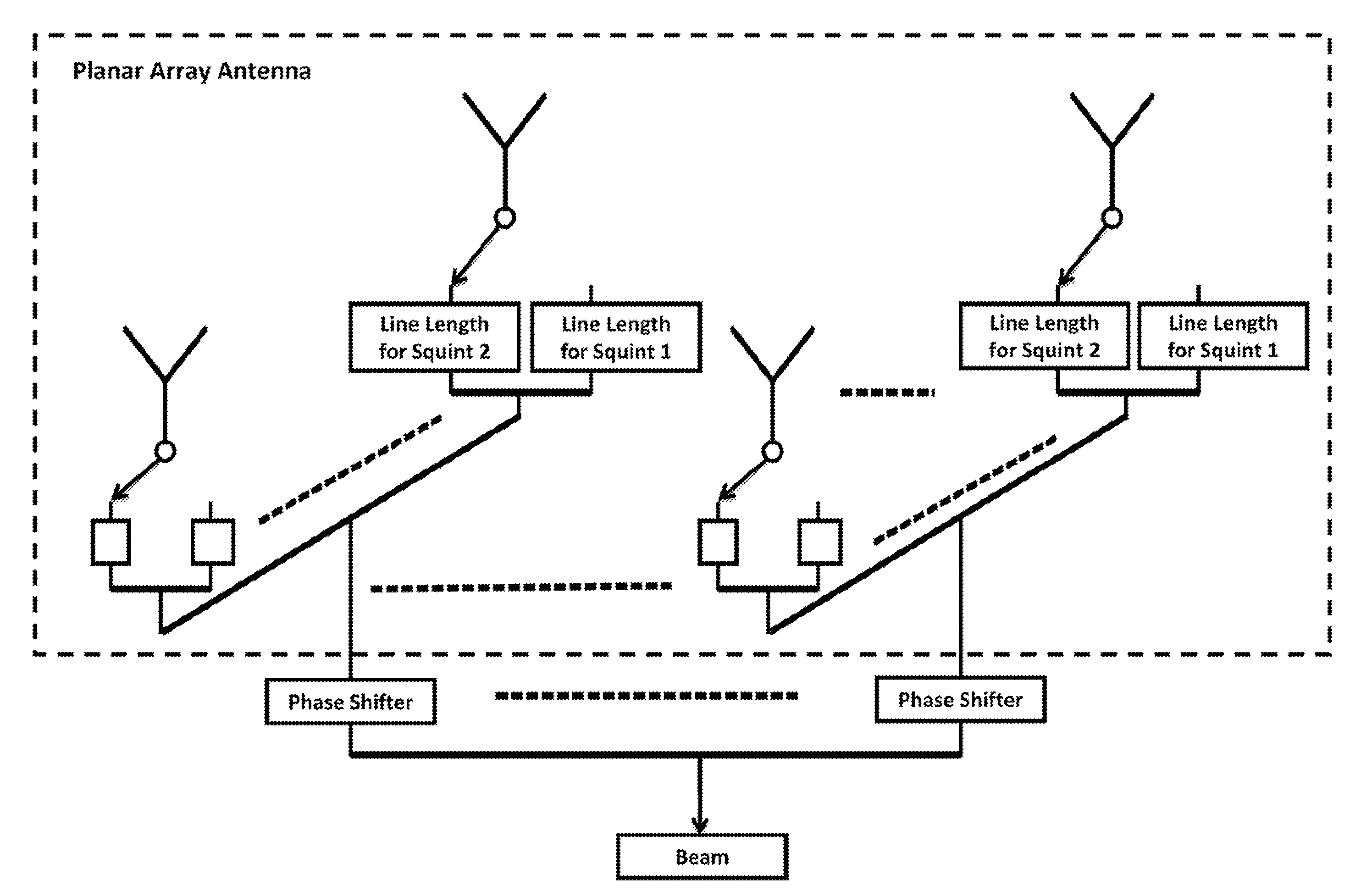
[0025]A user of communications satellite services often communicates with multiple satellites in GEO orbit 10 simultaneously. To track a GEO satellite 20 accurately with a planar array 30 for an antenna system on the earth 40, the phases of each element in the array must be controlled, which calls for a very complicated phase control system especially for a large array. Since many of the satellites 20, 22 that most users communicate with are in the GEO orbit 10, a planar array that scans the beam only in one plane can be used if the satellites are located in the cardinal plane of the array's sin θ space (directional cosine coordinate system). The geometry of the problem is depicted in FIG. 1. FIG. 2 shows that the cardinal planes 60, 65 of a planar array, whose elements are located on a rectangular grid, are simply the X and Y axis of the array 80. So, if the Y axis is the vertical axis of the array in FIG. 1 then an embodiment of the invention, for example, will only scan the beam ...


PUM


Abstract

A method for electronically scanning a predetermined geostationary orbital arc segment around the earth with an antenna system. The antenna system includes a planar array. A number of fixed electronic squints is selected. Lengths of the total plurality of fixed delay line lengths are generated for the planar array based on the number of fixed electronic squints. All of the antenna elements in the planar array for the mobile earth station are fitted with the generated lengths. The orbital arc segment is electronically scanned with a single linear scan with the planar array. This method is extendable to the case of multiple beams by adding additional phase shifters at each column and keeping the number of fixed line lengths the same, regardless of the number of additional beams.

Description

CROSS-REFERENCE TO RELATED APPLICATION[0001]This application claims priority to, U.S. Provisional Patent Application Ser. No. 60 / 883,562, entitled “MULTIBEAM GEOSTATIONARY SATELLITE COMMUNICATIONS ARRAY” to Rao et al.TECHNICAL FIELD[0002]The invention relates generally to a method of designing an antenna array, and more particularly, to a method for designing a planar array antenna for scanning a beam in one-dimension to communicate with one or more geostationary satellites.DESCRIPTION OF RELATED ART[0003]The users of communication satellite services use a fixed or mobile earth station, located on the ground, on the sea, or in the air to communicate with a satellite. Often, a user (e.g., a ship) needs to communicate with several satellites simultaneously. A separate antenna is used to communicate with each satellite. A planar array antenna (i.e., one made up of N×M elements) can in principle be used to communicate with several satellites simultaneously by generating multiple indepen...

Claims


Application Information

Patent Timeline
IPC IPC(8): H01Q3/00H01Q3/34
CPCH01Q3/2605H01Q21/061H04B7/18517
Inventor RAO, JAGANMOHAN B. L.MITAL, RASHMIPATEL, DHARMESH P.PARENT, MARK G.TAVIK, GREGORY C.
Owner NAVY USA AS REPRESENTED BY THE SEC OF THE THE
Features
  • R&D
  • Intellectual Property
  • Life Sciences
  • Materials
  • Tech Scout
  • Unparalleled Data Quality
  • Higher Quality Content
  • 60% Fewer Hallucinations
Learn More