
Calibrating digital pens

a digital pen and pen body technology, applied in the direction of input/output for user-computer interaction, instruments, computing, etc., to achieve the effect of improving the accuracy of reading the stroke of the pen

Inactive Publication Date: 2010-02-02
HEWLETT PACKARD DEV CO LP
View PDF10 Cites 18 Cited by
  • Summary
  • Abstract
  • Description
  • Claims
  • Application Information

AI Technical Summary

Benefits of technology

The present invention provides a method for calibrating a digital pen to compensate for differences in position between the pen and the paper it is used on. This method allows for accurate data capture regardless of the orientation of the pen. The calibration data takes into account factors such as pen specific factors and user specific factors, including the angle of inclination of the pen and the rotation of the pen relative to the paper. By repeatedly calibrating the pen over time, a high level of accuracy can be maintained. The method can be used in a variety of applications, such as data capture on digital paper or other media.

Problems solved by technology

This is not always the case due to manufacturing tolerances in the production of digital pens.

Method used


Image

  • Calibrating digital pens
  • Calibrating digital pens
  • Calibrating digital pens

Examples


Embodiment Construction

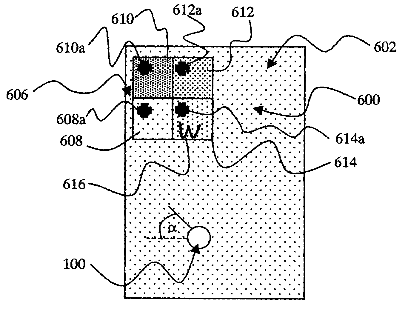
[0072]Referring now to FIGS. 1, 4a, 4b and 6 to 9, a sheet of digital paper 600 for use with the digital pen 100 comprises position location pattern 602 of dots as described in relation to the prior art and a calibration area 606 that has regions 608, 610, 612, 614 of pattern. The pattern in each of the regions 608, 610, 612, 614 is rotated in successive equi-angular steps, in this case 90° steps, away from alignment with the pattern 602 upon the paper, i.e. 0°, 90°, 180°, 270°. It will be appreciated that the rotation of the pattern could be at larger or smaller angular steps depending upon the accuracy of the calibration desired, and that there may be fewer, or more, regions with pattern at different rotations. The regions 608, 610, 612, 614 may represent a small fraction of the area of a page of the sheet 600. The fraction may be for example be a 1 cm by 1 cm area. It will be appreciated that other size of area may be suitable.

[0073]Indeed, in an alternative embodiment a calibrat...


PUM


Abstract

A method of calibrating a digital pen (100) comprises the steps of:i) acquiring calibration data indicative of parameters indicative of an offset between a nib (108) of the pen (100) and a field of view (124) of a camera (114) whilst the pen is in use; andii) using the calibration data to compensate for the offset in subsequently acquired pen usage data.A digital pen, digital paper and software for calibrating a digital pen and a network comprising a digital pen are also disclosed.

Description

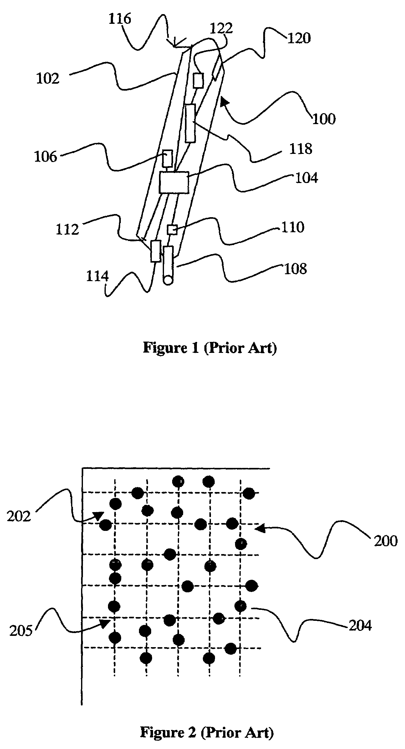
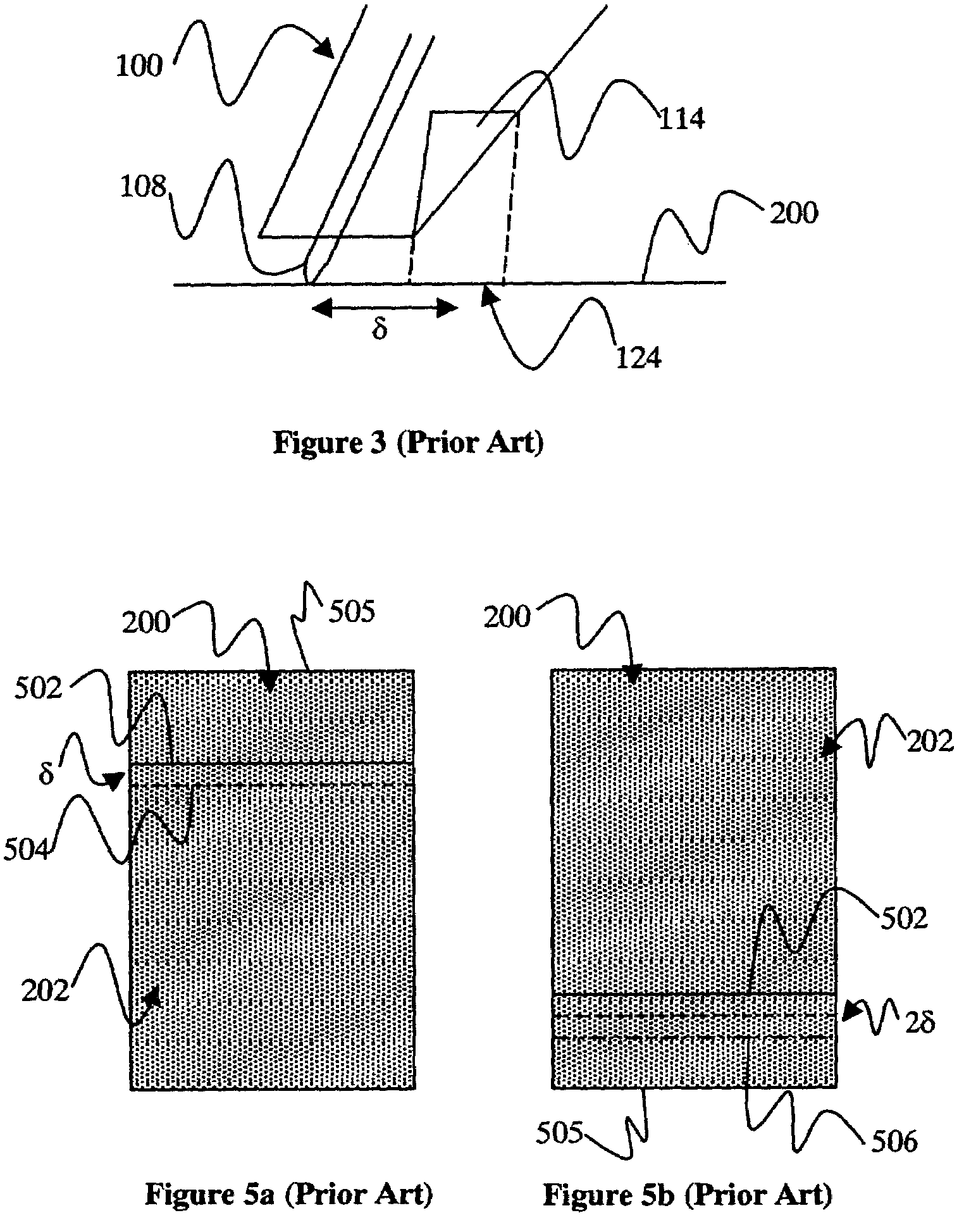
FIELD OF THE INVENTION[0001]This invention relates to calibrating digital pens, methods for use with calibrating digital pens and software for use with them.DISCUSSION OF THE PRIOR ART[0002]Referring now to FIGS. 1 to 5, a digital pen 100 adapted to write human readable ink in non-machine-readable IR transparent ink and to read a position dot pattern using infra-red light. The pen 100 has a housing 102, a processor 104 with access to memory 106, a removable and replaceable ink nib and cartridge unit 108, a pressure sensor 110 adapted to be able to identify when the nib is pressed against a document, an infra-red LED emitter 112 adapted to emit infra-red light, an infra-red sensitive camera 114 (e.g. a CCD or CMOS sensor), a wireless telecommunications transceiver 116, and a removable and replaceable battery 118. The pen 100 also has a visible wavelength warning light 120 (e.g. a red light) positioned so that a user of the pen can see it when they are using the pen, and a vibration u...

Claims


Application Information

Patent Timeline
Patent Type & Authority Patents(United States)
IPC IPC(8): G09G5/00G06F3/03G06F3/0354
CPCG06F3/0317G06F3/03545G06F3/0321
Inventor BOSCH, JOANBARTOLOME, EMILIANO
Owner HEWLETT PACKARD DEV CO LP
Learn More