Adaptive modulation method and coding rate control method

a modulation method and coding rate technology, applied in the field of radio communication systems, can solve the problems of increasing signal delay, deteriorating throughput, and longer transmission interval at the transmitter station

Inactive Publication Date: 2010-02-02
HITACHI LTD
View PDF7 Cites 2 Cited by
  • Summary
  • Abstract
  • Description
  • Claims
  • Application Information

AI Technical Summary

Benefits of technology

[0007]It is an object of the present invention to provide an adaptive modulation method and an coding rate control method for a radio communication system, wherein the former method controls an effective modulation level in accordance with the propagation path quality, while the latter method controls the coding rate without requiring repeated attempts at decoding in the receiver station, thereby eliminating the need for large processing capabilities in the receiver station.
[0010]In this way, the modulation type and coding rate can be controlled in accordance with the propagation path quality without the need for repeatedly attempting the decoding in the receiver station.
[0011]As appreciated from the foregoing, the present invention provides an adaptive modulation and a coding rate control method which can control a modulation type and an coding rate in accordance with the propagation path quality without the need for repeatedly attempting the decoding in the receiver station.

Problems solved by technology

In the multi-level modulation techniques, a larger number of bits per symbol results in a higher maximum throughput on propagation paths of higher quality, whereas errors are more likely to occur when the propagation path quality degrades, giving rise to a problem of a largely deteriorated throughput.
Also, in the HARQ scheme, the transmitter station must determine whether a retransmission should be done after the receiver station has completed the decoding, thereby causing a longer interval of transmission at the transmitter station, and a resulting increase in signal delay.

Method used


Image

  • Adaptive modulation method and coding rate control method
  • Adaptive modulation method and coding rate control method
  • Adaptive modulation method and coding rate control method

Examples


first embodiment

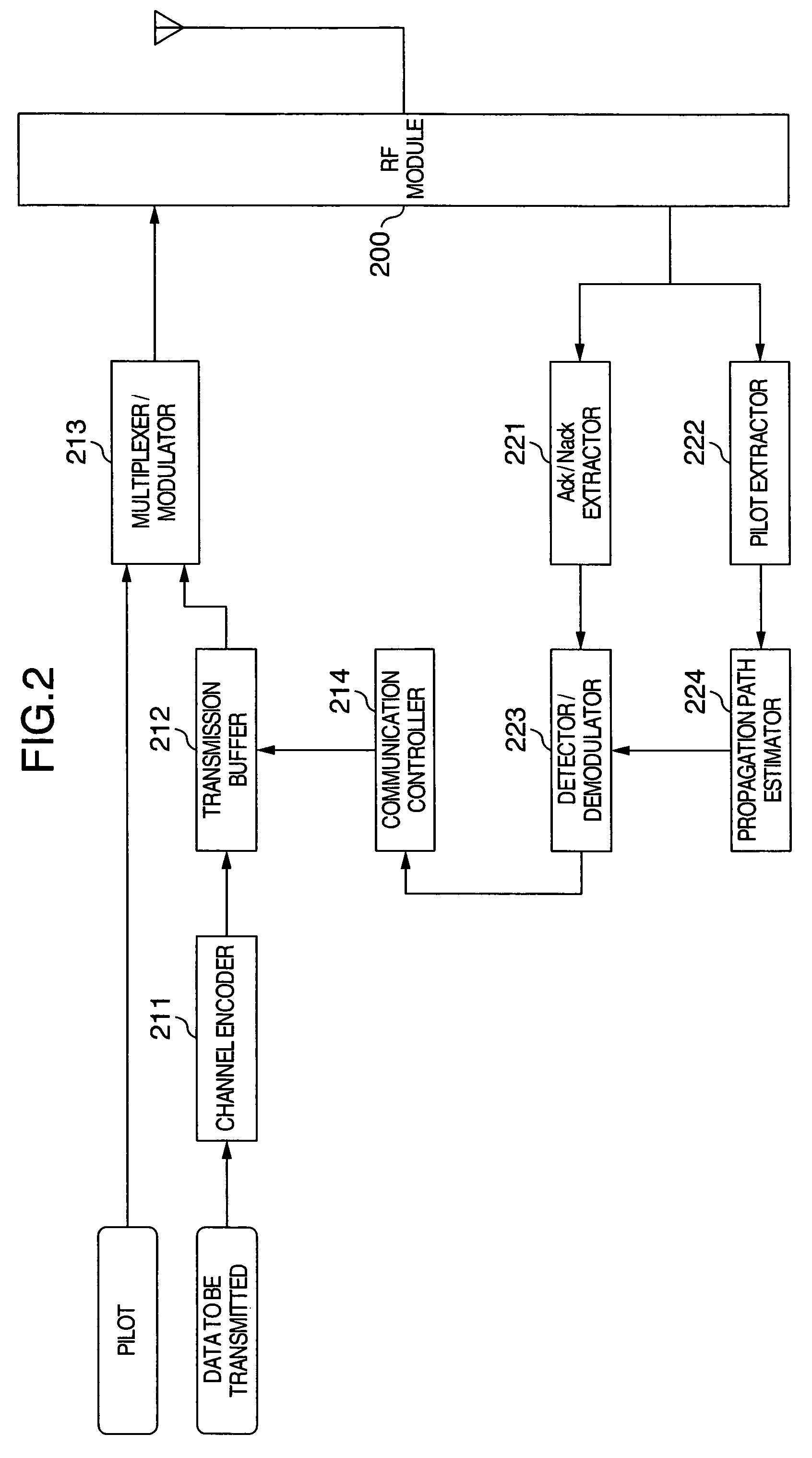
[0042]The configuration of the transmitter station and the flow of signal processing in the present invention will be described with reference to FIG. 2.

[0043]In the transmitter station illustrated in FIG. 2, data to be transmitted is first encoded in a channel encoder 211, and accumulated in a transmission buffer 212. The signal accumulated in the transmission buffer 212 is divided into sub-frames which are inputted to a multipliexer / modulator 213 when a continued transmission is instructed from a transmission controller 214 or when no instruction is issued from the transmission controller 214, such as in the first transmission, and multiplexed with a pilot signal. The resulting signal is modulated in accordance with a predefined modulation type, and transmitted from an RF module 200.

[0044]In the transmitter station illustrated in FIG. 2, a pilot signal is extracted by a pilot extractor 222 from among signals received at the RF module 200, and an amplitude and phase fluctuation inf...

second embodiment

[0052]The configuration of the transmitter station and the flow of signal processing in the present invention will be described with reference to FIG. 5.

[0053]In the transmitter station illustrated in FIG. 5, data to be transmitted is first encoded in a channel encoder 211, and accumulated in a transmission buffer 212. The signal accumulated in the transmission buffer 212 is divided into sub-frames which are inputted to a multipliexer / modulator 213 when a continued transmission is instructed from a transmission controller 214 or when no instruction is issued from the transmission controller 214, such as in the first transmission, and multiplexed with a pilot signal. The resulting signal is modulated in accordance with a predefined modulation type, and transmitted from an RF module 200.

[0054]In the transmitter station illustrated in FIG. 5, a pilot signal is extracted by a pilot extractor 222 from among signals received at the RF module 200, and an amplitude and phase fluctuation inf...

third embodiment

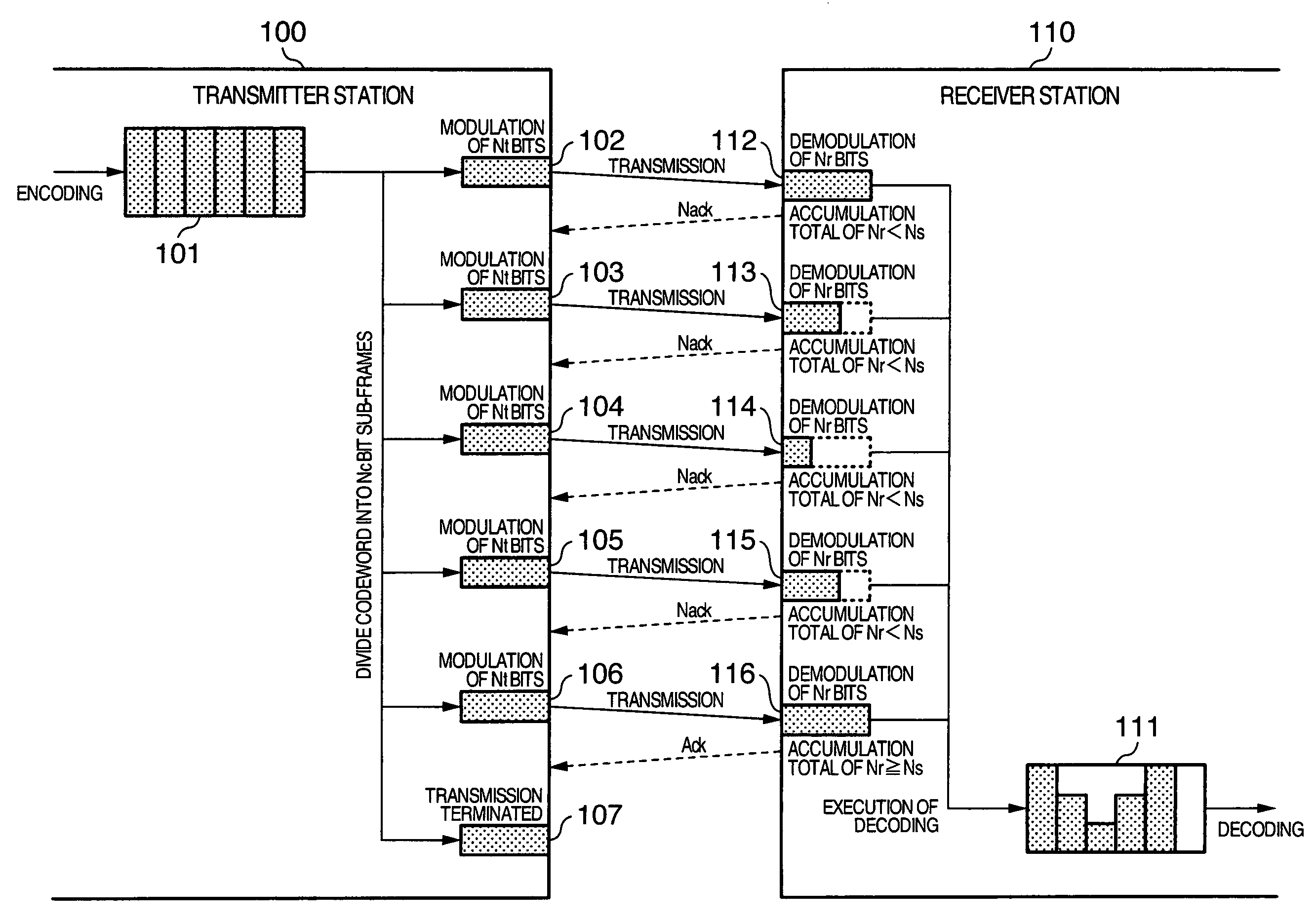
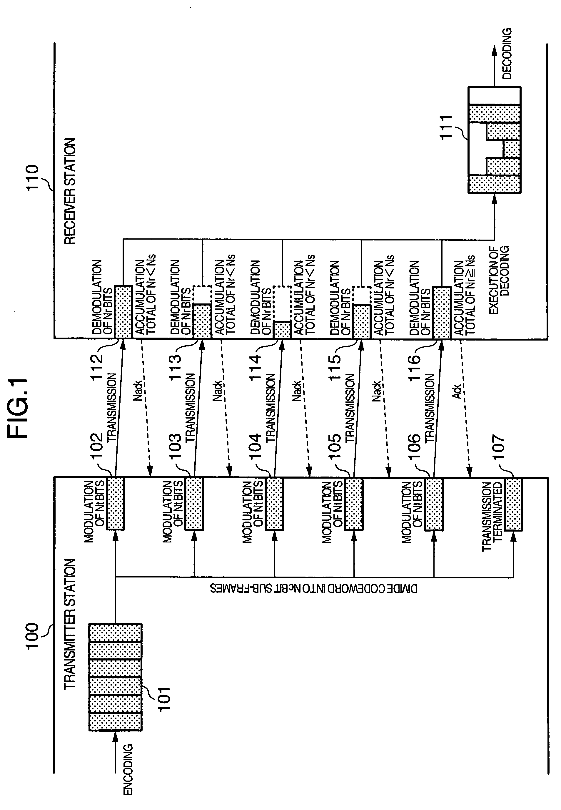
[0060]FIG. 7 in turn is a schematic diagram illustrating the flow of signal processing in the present invention.

[0061]In the third embodiment, the number Nt of bits for use in the modulation per sub-frame, and the number Nr of bits resulting from the demodulation per sub-frame are both variable. The transmitter station determines the number Nt of bits for use in the modulation per sub-frame, and whether to terminate the transmission of a codeword or not. The receiver station in turn determines the number Nr of bits resulting from the demodulation per sub-frame, and whether to decode a received signal. The third embodiment of the present invention performs the processing similar to that in the second embodiment of the present invention except that the transmitter station controls a modulation type in accordance with the information of Nr notified from the receiver station. In the third embodiment of the present invention, the transmitter station utilizes the notified Nr, modulates a ...


PUM


Abstract

In a radio communication system, transmitter and receiver stations share information on a maximum number of bits communicated per symbol. The transmitter station encodes a signal with sufficient error correcting capabilities to create a codeword. The transmitter station allocates the bits from the codeword to each symbol, modulates the symbols using a modulation type which processes symbols each having a number of bits equal to or smaller than the maximum number of bits per symbol, and transmits the modulated symbols. The receiver station demodulates the symbols using a modulation type which processes a larger number of bits per symbol as the transmission path quality is higher from among modulation types which process symbols having a number of bits equal to or smaller than the maximum number of bits per symbol.

Description

INCORPORATION BY REFERENCE[0001]The present application claims priority from Japanese application JP2005-013468 filed on Jan. 21, 2005, the content of which is hereby incorporated by reference into this application.BACKGROUND OF THE INVENTION[0002]The present invention relates to a radio communication system in which the quality of propagation paths varies over time, and more particularly, to a modulation method adapted to the varying quality of propagation paths and a method of controlling the coding rate of a channel code.[0003]For increasing the amount of information transmitted per unit time in a radio communication system, multi-level modulation techniques are known for transmitting a plurality of bits of information per symbol.[0004]In the multi-level modulation techniques, a larger number of bits per symbol results in a higher maximum throughput on propagation paths of higher quality, whereas errors are more likely to occur when the propagation path quality degrades, giving r...

Claims


Application Information

Patent Timeline
Patent Type & Authority Patents(United States)
IPC IPC(8): H04L5/12
CPCH04L1/0003H04L1/0023H04L1/1671H04L1/1812
Inventor TAMAKI, SATOSHIYANO, TAKASHIHANAOKA, SEISHISAITO, TOSHIYUKI
Owner HITACHI LTD
Why Eureka
Try Eureka