Method, apparatus and system for measuring a welding-groove position

a technology for measuring equipment and welding grooves, applied in the direction of distance measurement, manufacturing tools, instruments, etc., to achieve the effect of measuring and detecting the welding groove position quickly with accuracy

Inactive Publication Date: 2010-02-02
KAWASAKI HEAVY IND LTD +1
View PDF9 Cites 18 Cited by
  • Summary
  • Abstract
  • Description
  • Claims
  • Application Information

AI Technical Summary

Benefits of technology

[0009]Here, the relative positions between the projected slit-light images in the three-dimensional data can be defined from the shapes, arrangement, etc. of the thin members. Therefore, even if the projected slit-light images acquired are not sufficiently accurate due to the above-mentioned influences, the relative positions will not be influenced by the same. Thus, the aspects of the present invention utilize the relative position along with the three-dimensional data to reduce these influences.
[0046]In another aspect of the invention, the sensor rotating device of the system may be a robot that includes one movable arm or movable arms, and the welding-groove measuring sensor may be attached to a tip-end portion of the movable arm or movable arms. Thereby, the welding-groove measuring sensor can be easily moved to a suitable position to measure the three-dimensional welding groove position.

Problems solved by technology

Therefore, even if the projected slit-light images acquired are not sufficiently accurate due to the above-mentioned influences, the relative positions will not be influenced by the same.

Method used


Image

  • Method, apparatus and system for measuring a welding-groove position
  • Method, apparatus and system for measuring a welding-groove position
  • Method, apparatus and system for measuring a welding-groove position

Examples


Embodiment Construction

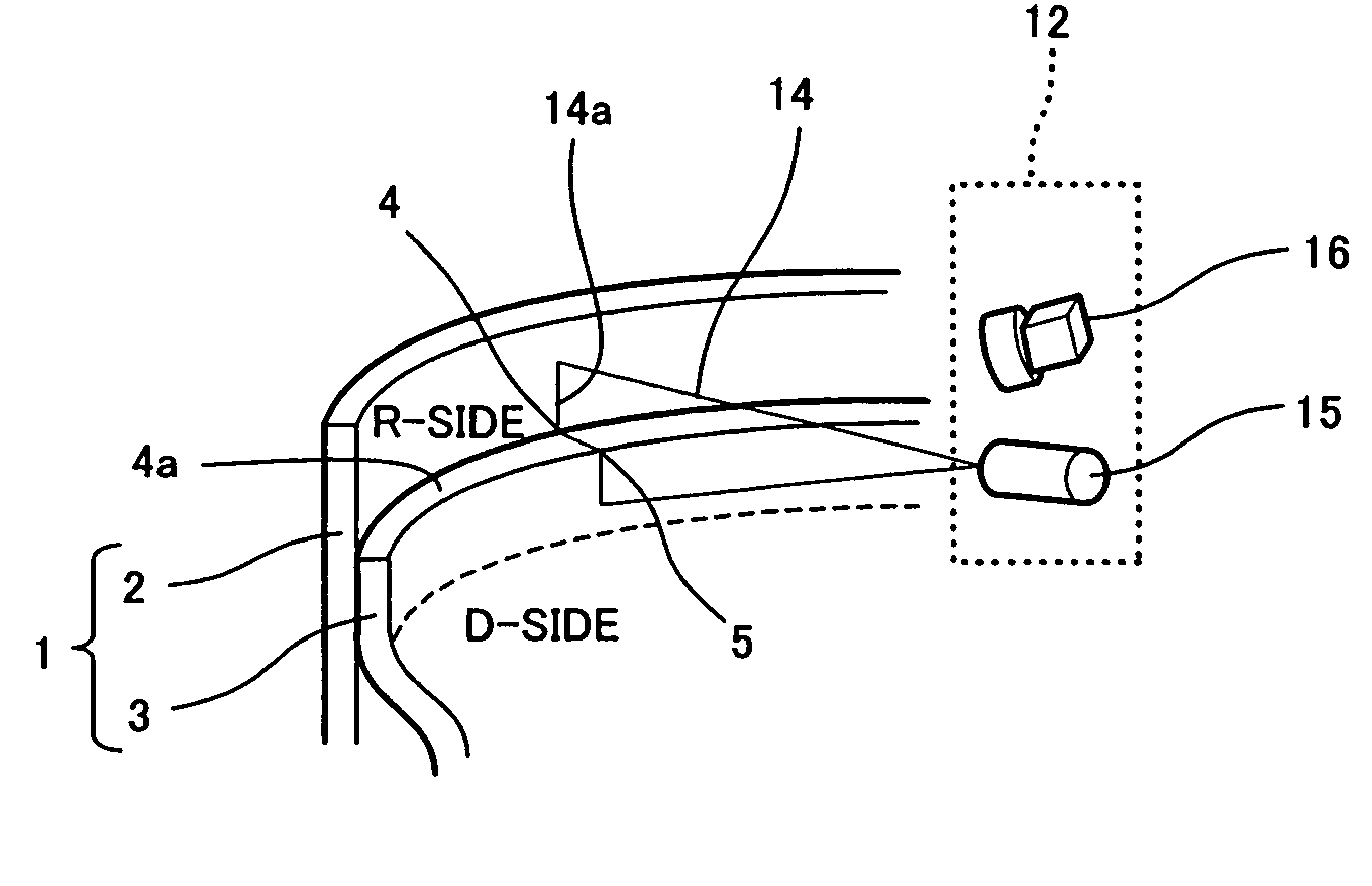
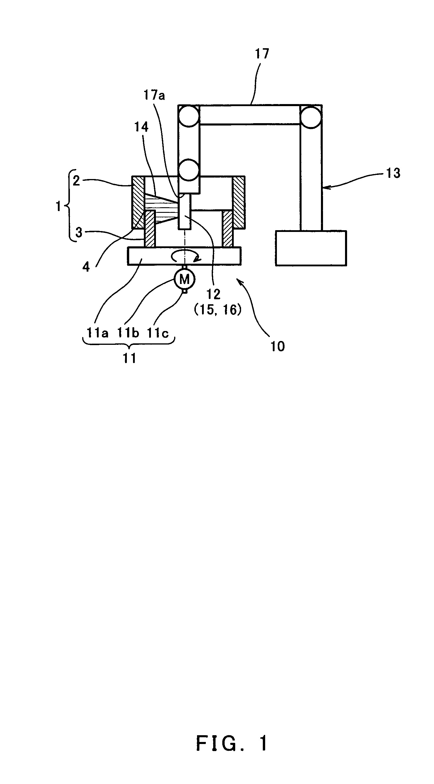
[0067]FIG. 1 is a schematic view showing a configuration of a welding-groove measurement system according to one embodiment of the invention. As shown in FIG. 1, a measuring object 1 typically includes two hollow cylindrical members with different diameters. Typical examples of these members are a rim and a disk of an automobile wheel. The cylindrical member 3 of a smaller diameter (hereinafter, referred to as “a welding object”) is fitted inside the cylindrical object 2 of a larger diameter, with an overlapped section which is designed to be fillet-welded to join the members together. The measuring object 1 may be any other suitable shape and is not limited to a cylindrical shape.

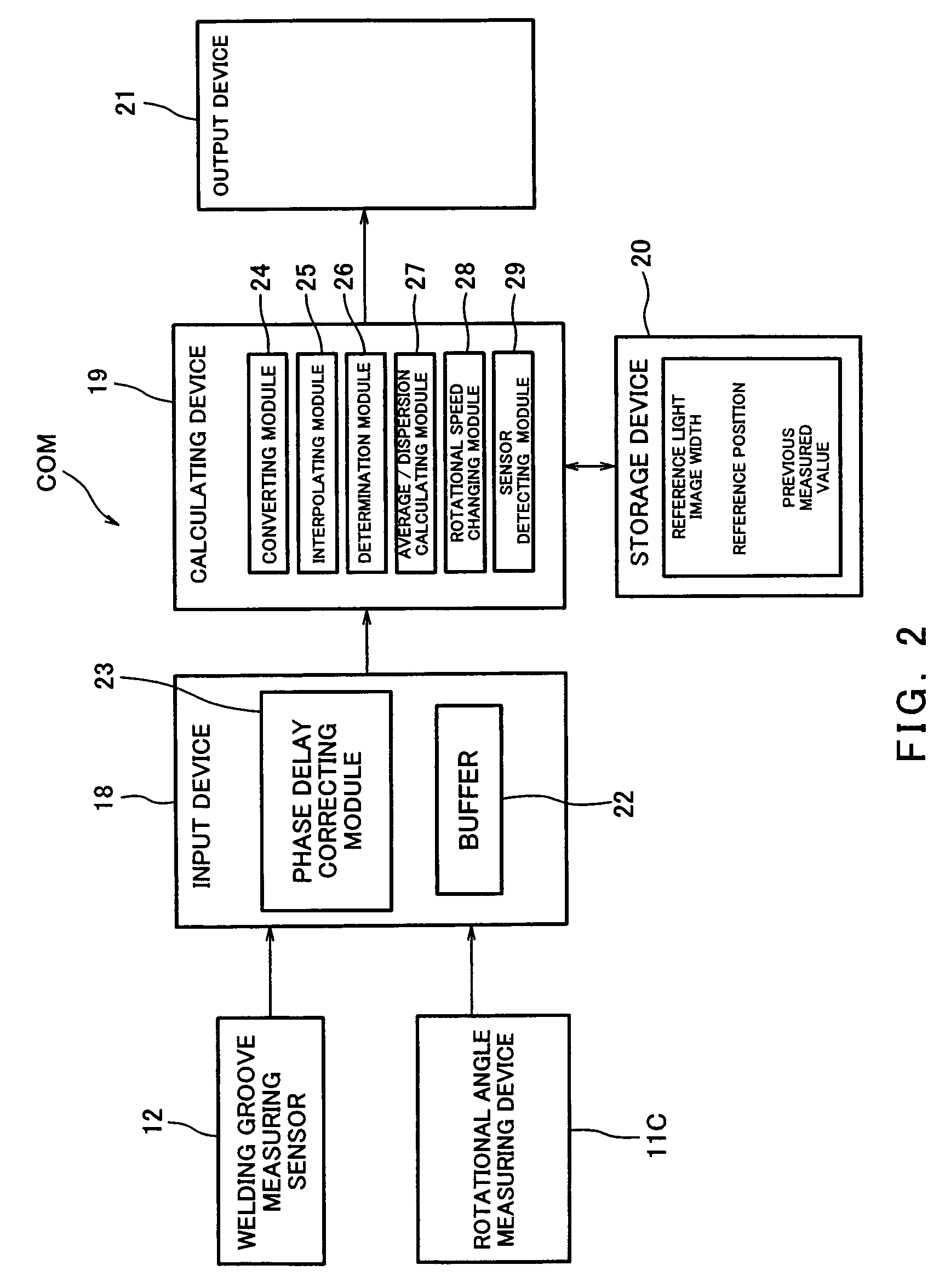
[0068]In this embodiment, the welding-groove measurement system 10 includes a rotating device 11 for rotating the measuring object 1, a welding-groove measuring sensor 12 for measuring a welding-groove position of the welding object 3, and a positioning device 13 that supports the welding-groove measuring ...


PUM

PropertyMeasurementUnit
widthaaaaaaaaaa
displacementaaaaaaaaaa
shapesaaaaaaaaaa

Abstract

A method of measuring a welding-groove position for an over-lapped fillet welding of thin members, comprising a projection step of projecting a slit light so that the slit light is projected on both the thin members crossing a welding-groove face, a two-dimensional image acquisition step of capturing the slit-light image projected on each of the thin members as two-dimensional images; a three-dimensional conversion step of converting the two-dimensional images into three-dimensional images using a predetermined three-dimensional conversion parameter, and a calculation step of calculating the welding-groove position based on the three-dimensional data of the projected slit-light images, and relative positions between the projected slit-light images in the three-dimensional data defined by shapes and arrangement of the thin members.

Description

CROSS-REFERENCE TO RELATED APPLICATION[0001]This application is based on and claims priority to Japanese Patent Application No. 2005-009767, filed Jan. 18, 2005, the entire disclosure of which is incorporated herein by reference.TECHNICAL FIELD[0002]The present invention relates to a method, apparatus, and system for measuring a welding-groove position of work pieces to be welded, using a sensor that projects a slit light or scans with a spot light, etc.BACKGROUND OF THE INVENTION[0003]A conventional automated welding system using a robot, etc., is configured so that it measures a welding-groove position of work pieces using a sensor that projects a slit laser or scans with a spot laser, etc., before performing welding, and calculates (or corrects) an instruction value for the welding robot based on the measurement, in order to compensate for individual specificity and the misalignment of the work pieces.[0004]For example, Japanese Patent No. 3228777 discloses an apparatus that incl...

Claims


Application Information

Patent Timeline
Patent Type & Authority Patents(United States)
IPC IPC(8): G06K9/00A47J36/02B23K26/00G01C3/14
CPCB23K9/1274
Inventor KUBO, SADAOSHIMADA, TADAOONOUE, KAZUHIKOUEHARA, HIROTAKAKINOSHITA, HIROTAKASUZUKI, YUKIMITSUARITA, ICHIRO
Owner KAWASAKI HEAVY IND LTD
Why Eureka
Try Eureka