Remote controller for portable electronic device

a remote controller and electronic device technology, applied in the direction of computer control, instruments, cathode-ray tube indicators, etc., can solve the problems of increasing the difficulty of properly secure the window, the window becomes prone to be lifted up and finally detached from the device body, and the assembly time is longer, so as to simplify the operation of the user and be easily seen by the user

Inactive Publication Date: 2010-02-02
SONY EMCS MALAYSIA SDN BHD HOUSE SERVICE +1
View PDF2 Cites 1 Cited by
  • Summary
  • Abstract
  • Description
  • Claims
  • Application Information

AI Technical Summary

Benefits of technology

[0012]The display means is preferably in the form of window means housed by the body means, said window being in the form of a curved surface extending at least 180 degrees around the body means. In a preferred arrangement the window extends up to approximately 270 degrees around the body means and is generally circular in cross section. An angle in the range of about 180 to about 270 degrees in preferred. The display window preferably forms a structural component of the body means to provide strength and / or rigidity to the body.
[0016]According to certain aspects of the invention, a wider and stronger display window is achieved by adopting a part cylindrical or tubular structure for the window. This not only provides an inherently stronger structure than the conventional flat plate, but also allows a new method of assembly for the control device. Especially, the curved window may be assembled relative to the device body in a simple sliding action in the longitudinal direction of the body, and then held in place mechanically, for example by clip, snap-lock and other measures within the competence of a personal of ordinary skill in the art, without the need for adhesive. Thus, the assembly process is simplified and speeded up. Moreover, the curved window forms part of the body structure, so the final product becomes stronger and more resilient to shock. This is important as there is tendency for the user to touch the window in normal use. With a tubular window in accordance with the invention, any force applied to the window, in the direction of arrow Z in FIG. 2, is transmitted to the wall of the body without being transferred to the delicate display, as can happen with prior art flat windows. So, the display is better protected. The construction of the invention can also help in reducing the risk of damaging ESD (electrostatic discharge).
[0017]According to other aspects of the invention, the need for a dedicated set of mode buttons is eliminated, which saves components and frees space for greater miniaturization and / or increasing the window size, both of which are desirable to the user. Device size reduction can be done without compromising functionality in any way. Additional functions can be incorporated in later models simply by changing the jog dial to one having more positions. This avoids significant re-design such as would be necessary to accommodate extra mode buttons. Valuable space is also conserved by the control of the invention, so adding more functions may not require increasing the overall size of the device.
[0019]The use of a jog dial control for mode selection greatly simplifies operation for the user. In particular, it provides an immediate, intuitive operation as the mode selected is associated directly with the analogue position of the jog dial, which is readily seen by the user. There is also no need for repeated pushing of a mode select button while simultaneously checking the display to ascertain the current mode at each push, as per the above-mentioned related art.

Problems solved by technology

With increasing miniaturization, and having only the narrow frame portion to which adhesive can be applied, it becomes increasing difficult to properly secure the window.
As such, the window becomes prone to be lifted up and finally detached from the device body after extended use.
Furthermore, the provision of a set of dedicated mode buttons, as seen in FIG. 6, for the various functions hinders miniaturization, requires a large number of components and hence longer assembly time, as well as making operation more complicated for the user.
According to a related art, even the alternative of a common mode selection button that is repeatedly pressed to cycle through a list of modes, also disadvantageously requires the user to pay attention to the display so as to know the current mode selected.
Hence, operation of such devices is overly complicated, their assembly in manufacture is fiddly and time-consuming, while their structure is vulnerable to breakage.

Method used


Image

  • Remote controller for portable electronic device
  • Remote controller for portable electronic device
  • Remote controller for portable electronic device

Examples


Embodiment Construction

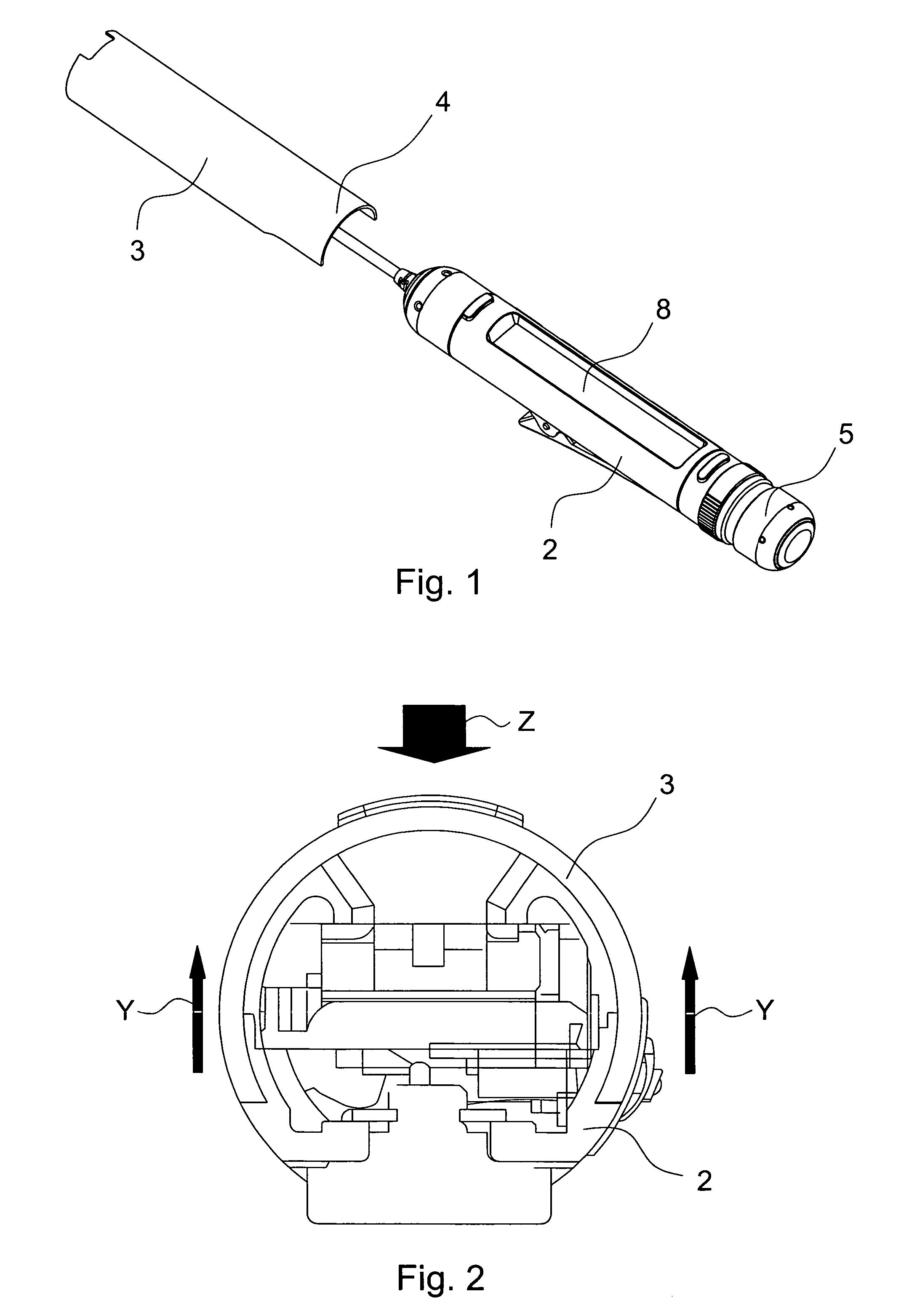
[0025]Referring first to FIG. 1, a remote control device 1 for operating a Sony Walkman or the like has an elongated and generally cylindrical shaped body 2 which is adapted to house a display window 3 over LCD display 8. The display window 3 is fed into the elongated body 2 in the direction of arrow X, and one end 4 of the window is received in a correspondingly shaped recess (not shown) adjacent one end 5 of the body 2.

[0026]As best seen in FIG. 2, the display window 3 is circular in cross-section and extends approximately 270 degrees around the cylindrical body. The window 3 forms a structural component of the body to provide strength and rigidity to the remote control device 1. Additionally, when the angle subtended by the window 3 exceeds 180 degrees, it becomes much harder to forcibly dismantle the window in the direction of the arrows Y in FIG. 2.

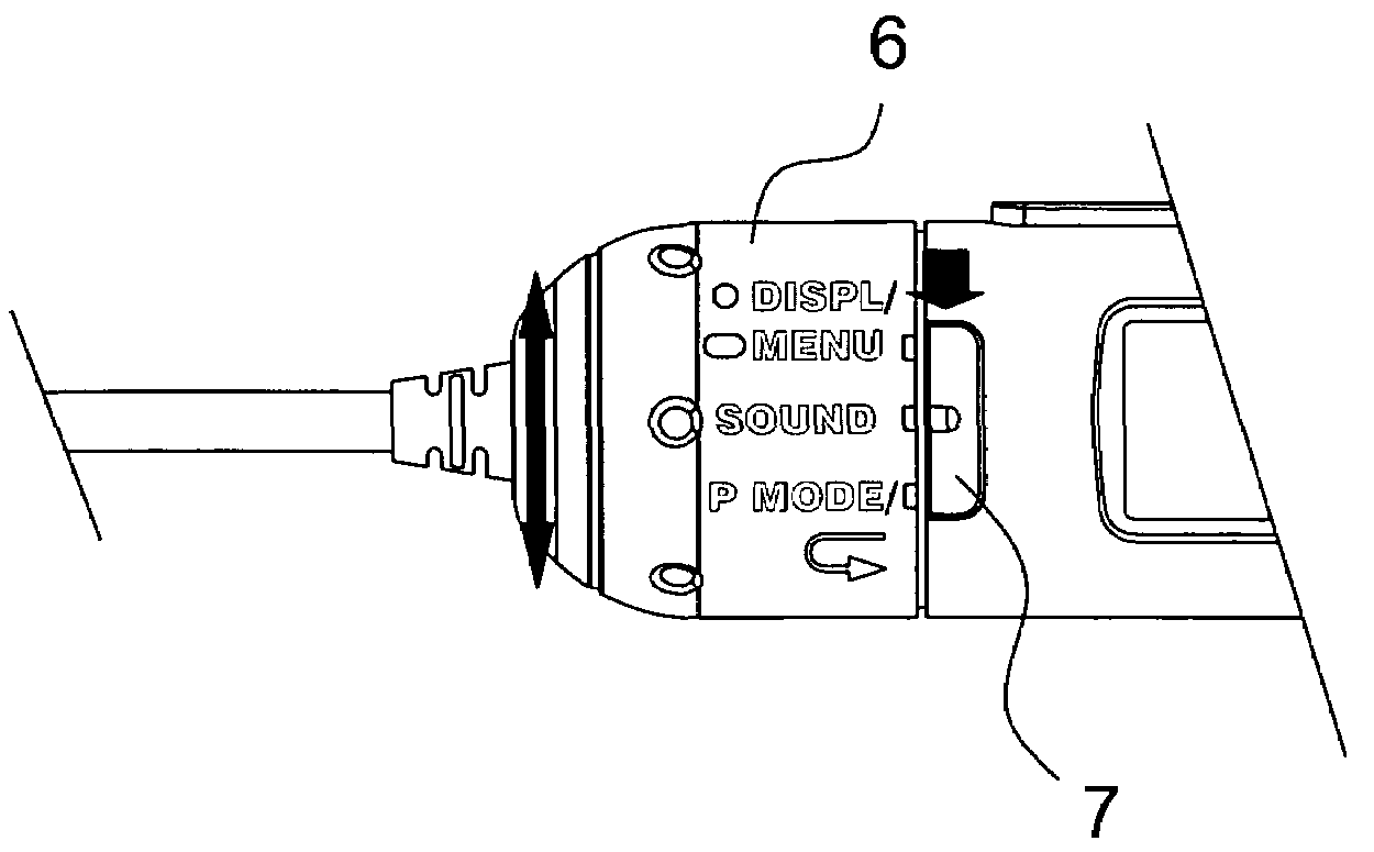
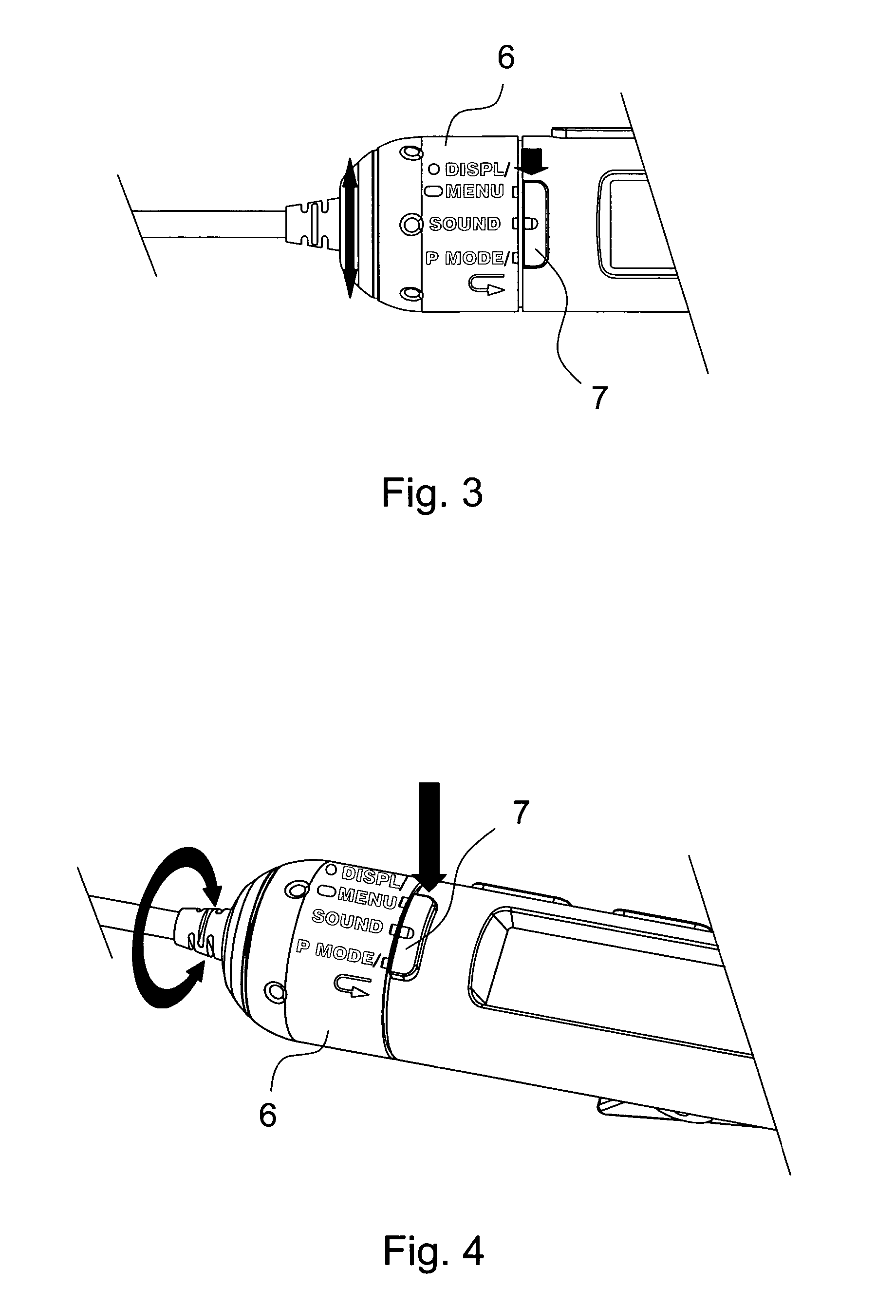
[0027]Referring to FIGS. 3 and 4, a rotatable selection means in the form of a jog dial 6 can be rotated to select any one of the m...


PUM


Abstract

A control device for operating electronic equipment having a generally elongated body and rotatable selection portion that is rotatable to any one of a plurality of operation mode positions. A display unit displays information associated with each mode, and a single common actuator activates the selected mode. The display unit may include a curved window that extends at least 180 degrees around the body.

Description

[0001]The present invention relates to a control device for operating electronic equipment, and in particular, although not exclusively, relates to a remote controller for operating a Sony Walkman, music player or like personal electronic device. Such remote controllers are normally incorporated in the cable of a headset for the personal electronic device and designed to be clipped to the user's clothing for convenient access.BACKGROUND TO THE INVENTION[0002]There are many such control devices currently on the market. With these control devices it is usual to select a mode such as “menu”, “display”, “sound” or “play” by pressing a digital button. A separate digital button is typically provided for each of the modes. The display means of the prior art devices is normally a flat LCD screen window which is fixed into position with the use of adhesive.[0003]A device of the above general type is known from Japanese Laid-Open Patent Application Publication No. JP-A-2002-93142, from which ...

Claims


Application Information

Patent Timeline
Patent Type & Authority Patents(United States)
IPC IPC(8): G05B15/00
CPCG11B19/027G11B33/10
Inventor YEAP, KOK ENGKIMOTO, HIROSHI
Owner SONY EMCS MALAYSIA SDN BHD HOUSE SERVICE
Why Eureka
Try Eureka