Method and system for flow detection and motion analysis

a flow detection and motion analysis technology, applied in television systems, instruments, color signal processing circuits, etc., can solve the problems of inability to recognize and analyze scenes which include flow, monitoring systems are not automated, and static and rigid target objects are difficult to detect, so as to achieve efficient and accurate detection and reduce false alarms

Inactive Publication Date: 2010-02-09
VERIFICON CORP
View PDF28 Cites 58 Cited by
  • Summary
  • Abstract
  • Description
  • Claims
  • Application Information

AI Technical Summary

Benefits of technology

[0017]According to an embodiment of the invention, the flow motion analysis estimates the motion present in a target area by analyzing a number of frames using motion vectors. The motion vectors are used to identify an initial or predicted flow motion region. To more accurately identify the flow motion region, the predicted flow motion region is refined. More specifically, the flow motion analysis according to the invention involves iterative refinements of the initially predicted flow motion region. These refinements are performed according to techniques known in the art, such as, thresholding and temporal filtering. These refinements increase the accuracy of the flow motion identification by reducing the effects of motion noise, referred to as non-flow motion, typically caused by foreign objects, such as, for example, an animal, person, or tree. Following refinement of the predicted flow motion region, a mask corresponding to the refined flow motion region is generated. The mask is then applied to unrefined, or raw, frames of the inputted video data to mask a flow motion region, referred to as a masked area. In a preferred embodiment, the masked area is further refined for increased accuracy, resulting in an identified flow motion region. This identified flow motion region is then analyzed to determine the characteristics of the flow motion.
[0018]Optionally, the motion of the inputted video data (i.e., the movement of the video camera), referred to as global motion, can be eliminated using a known camera-motion estimation method. According to this embodiment, the global motion is estimated and compensated to produce a frame with primarily motion vectors associated with the targeted area, referred to as local motion vectors. As such, the system is able to distinguish between undesired camera motion and target flow motion, thus increasing the system's overall robustness and accuracy.
[0023]According to another aspect of the invention, the system distinguishes between an image's flow motion and other motion caused by foreign objects, referred to as global motion. In addition, the system identifies and eliminates any camera motion caused by, for example, environmental factors, including but not limited to a rain, snow, earthquakes, or wind. Thus, the system reduces ambient motion and focuses on the flow motion region of the targeted area. Advantageously, this results in a more efficient and accurate alarm system having fewer false alarms caused by ambient motion unrelated to flow motion.

Problems solved by technology

Generally, these techniques are limited to the detection of static and rigid target objects with low variance in color and shape.
Further, these monitoring systems are not automated, requiring constant supervision by one or more operators.
As such, these systems can not be used to recognize and analyze scenes which include a flow.
Further, certain flows can be dangerous or even deadly, thus requiring constant monitoring and supervision.
However, such a matching technique may not result in an accurate estimation of the physical location change of an object over a number of video frames, known as ‘true’ motion.
While true motion estimation is critical to flow motion detection, systems employing these methods fail to distinguish between flow motion of a targeted object and other ambient non-flow motion, such as the movement of trees, flying birds, rain, etc.
These and other foreign objects obstruct the targeted object resulting in significant occlusion problems.
Another drawback to existing video monitoring systems is the lack of efficient alarming capabilities.
Specifically, these systems do not provide alarms and warning messages, store and transmit detected signals, or control security devices.
In addition, due to bandwidth limitations, conventional systems can not process and transmit multi-channel video in real-time to multiple locations.
Thus, existing systems are limited in that they do not provide an efficient cross-layer optimization wherein the detection of an event and an alarm type are synchronized to transmit alarm data to an operator.

Method used


Image

  • Method and system for flow detection and motion analysis
  • Method and system for flow detection and motion analysis
  • Method and system for flow detection and motion analysis

Examples


Embodiment Construction

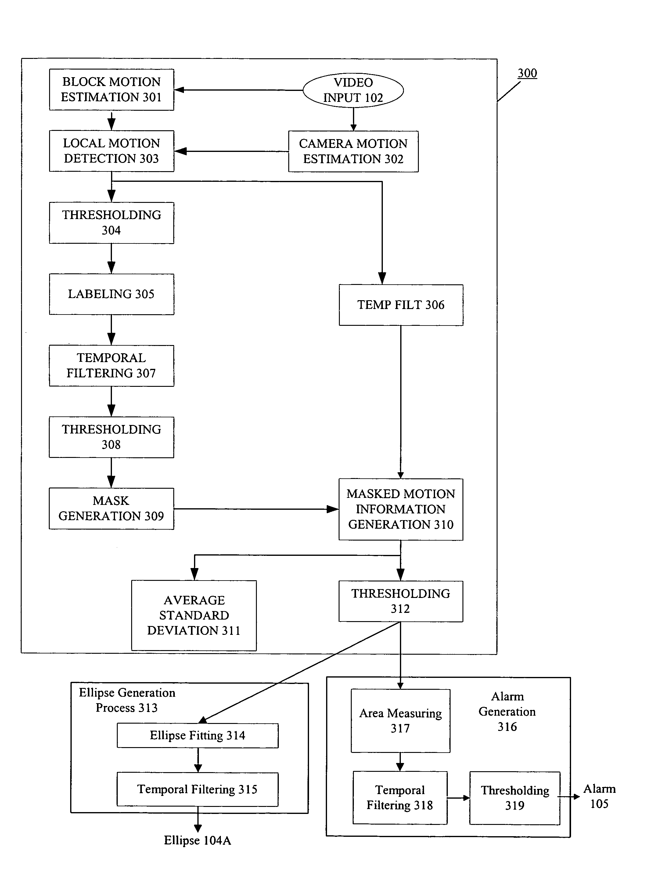
[0041]The present invention relates to methods, devices and systems for detecting and analyzing the motion of a flow, such as a mudslide.

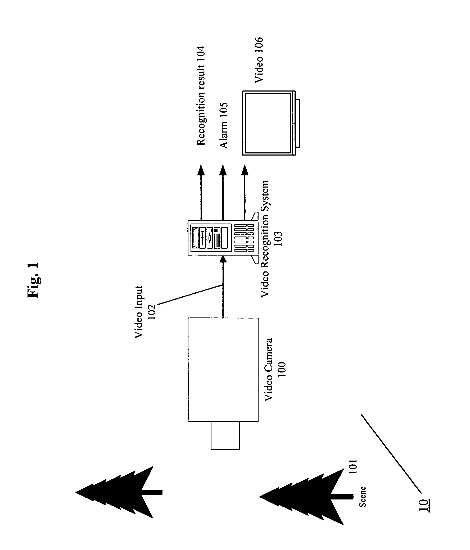
[0042]FIG. 1 illustrates an exemplary arrangement of components of a flow detection and motion analysis system 10 according to the invention. Specifically, FIG. 1 shows a video camera 100, well known in the art, positioned to monitor a scene 101 that may contain one or more events or objects of interest. It should be noted that although the embodiments of the present invention are described as using a video camera, one of ordinary skill in the art will readily appreciate that any image capturing device may be used. In addition, it is to be appreciated that the image capturing device may be positioned relative to the scene 101 in a variety of ways, such as above the scene in a satellite.

[0043]The video camera 100 provides a video input 102 to a communicatively connected computer, referred to as a video recognition system 103. The term “communicative...


PUM


Abstract

A surveillance system receives video data of a monitored scene and identifies flows of motion in the scene. Specifically, a video camera communicates with a video recognition system, which identifies a flow motion region of a monitored scene and determines characteristics of the identified flow motion region.

Description

CROSS-REFERENCE TO RELATED APPLICATION[0001]This application claims the benefit of U.S. Provisional Application No. 60 / 529,879, by Tiehan Lu, I. Burak Ozer, and Wayne Wolf, entitled “Method and Apparatus For Automatically Detecting Flows”, filed on Dec. 16, 2003. The entire disclosure of U.S. Provisional Application No. 60 / 529,879 is hereby incorporated herein by reference.FIELD OF THE INVENTION[0002]The present invention relates to methods and systems for providing real-time video surveillance of a monitored area so that flow motion, such as, for example, the flow of mud or debris may be recognized. More specifically, this invention relates to an automatic video analysis system for detecting a presence and characteristics of a flow in real time.BACKGROUND OF THE INVENTION[0003]Today, different types of sensor networks are used to create warning systems for natural disasters, such as flooding and land / mud sliding. Frequently, these systems include one or more video devices (i.e., ca...

Claims


Application Information

Patent Timeline
Patent Type & Authority Patents(United States)
IPC IPC(8): G06K9/00G06K9/46H04N5/14
CPCG06K9/00711G06T7/215H04N5/145G06K9/00771G06V20/40G06V20/52
Inventor LU, TIEHANOZER, IBRAHIM BURAKWOLF, WAYNE
Owner VERIFICON CORP
Why Eureka
Try Eureka