
Plow

a technology of plows and plows, which is applied in the field of plows, can solve the problems of time-consuming and laborious mounting and unloading of plows, slow plowing, and owners of many vehicles cannot obtain a conventional plow to fit their vehicles

Inactive Publication Date: 2010-02-16
JOHN D SHEPHERD LLC
View PDF48 Cites 22 Cited by
  • Summary
  • Abstract
  • Description
  • Claims
  • Application Information

AI Technical Summary

Benefits of technology

Enables quick and versatile snow removal in both directions, maintaining effective plowing performance over uneven terrain without tilting or pivoting, and providing consistent downforce for efficient snow clearing.

Problems solved by technology

It is mounted to the front of a truck or other vehicle at multiple attachment points, and it is time consuming to mount and unmount the plow.
Owners of many vehicles cannot obtain a conventional plow to fit their vehicle.
Plowing can be slow.
Known systems for applying a down force in a conventional plow are not fast and flexible enough to accommodate uneven or rough terrain.
Although plows have been designed to be pulled behind a vehicle, some of these have been light weight plows and have not been sturdy enough to handle heavy loads.
In addition, their light weight has permitted the plow to float rather than doing a good job of cleaning.

Method used


Image

  • Plow
  • Plow
  • Plow

Examples


Embodiment Construction

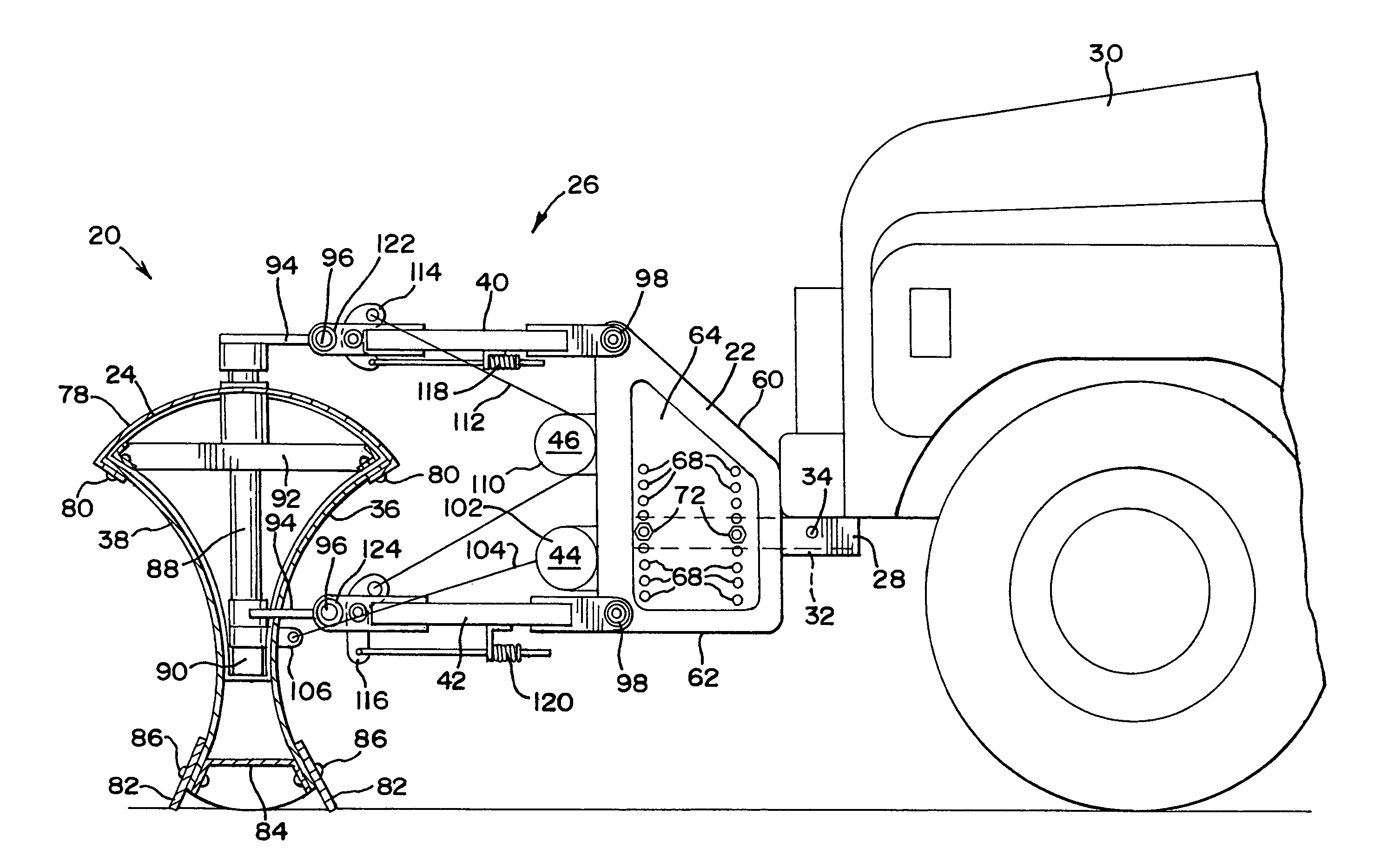
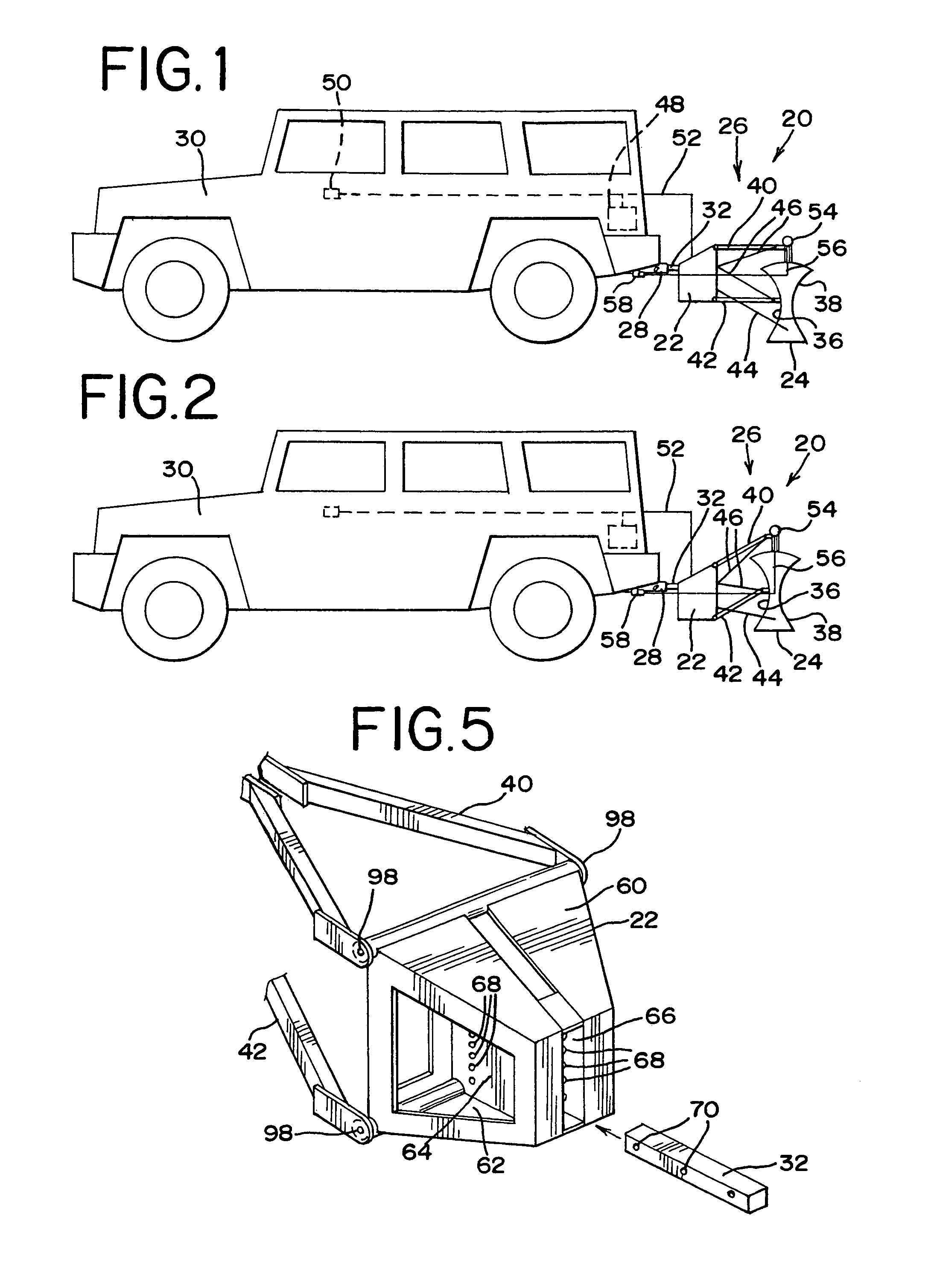
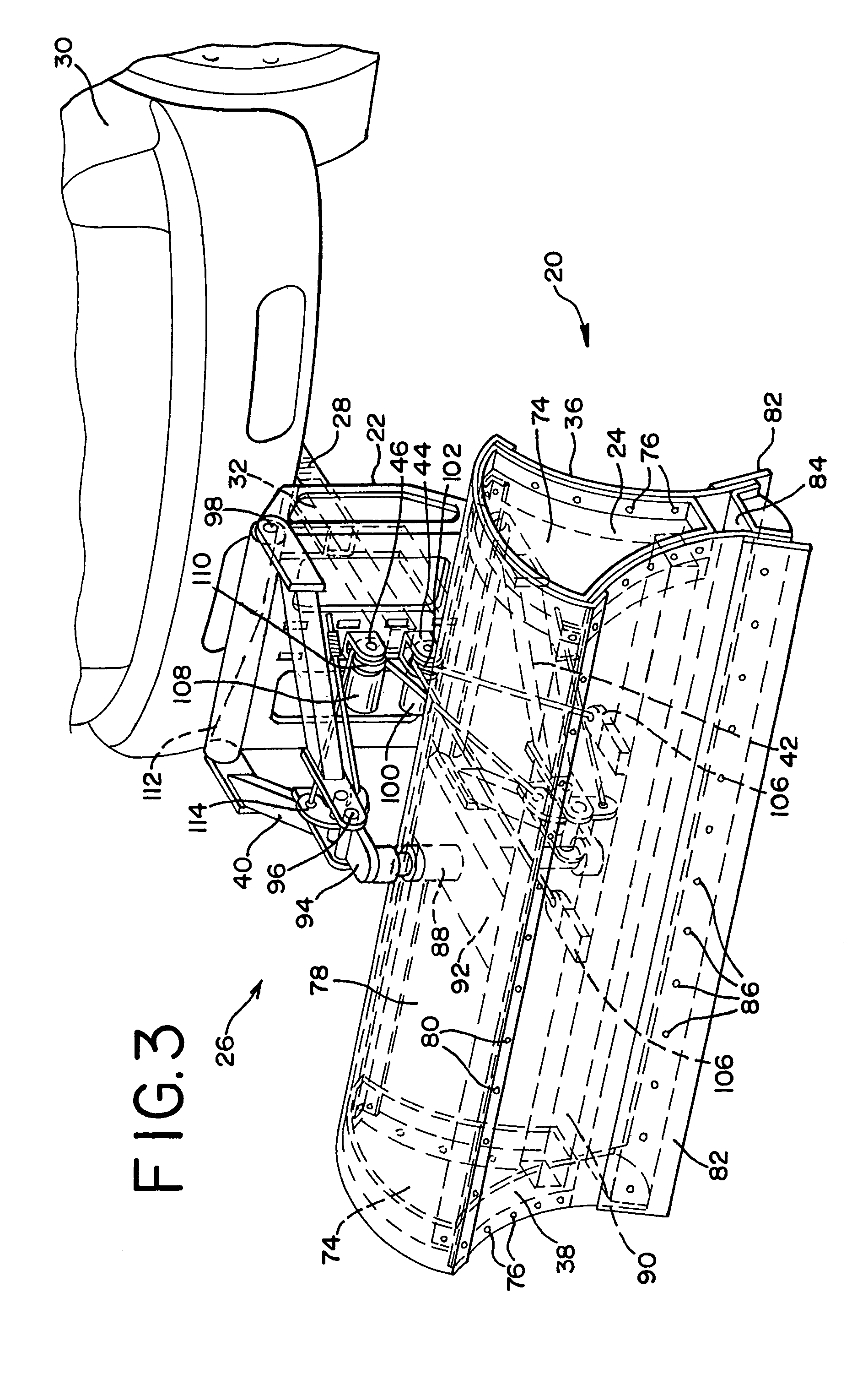
[0017]Having reference now to the drawing, and initially to FIGS. 1 and 2 there is illustrated in simplified diagrammatic form a plow generally designated as 20 and constructed in accordance with the principles of the present invention. In general, the plow includes a support or hitch box 22, a plow head 24 and a linkage 26 connected between the hitch box 22 and the plow head 24.

[0018]The plow 20 is a self contained stand alone unit that is easily mounted directly to a standard, tubular, two inch square cross section hitch receiver 28 of a vehicle 30. Although the illustrated vehicle 30 is a sport utility vehicle, a plow in accordance with the present invention may be used with any vehicle having a rear or a front hitch receiver, including trucks, passenger cars, all terrain vehicles, garden tractors and any others. Hitch receivers are usually mounted at the rear of a vehicle, and the plow of the present invention is normally intended to be mounted at the rear of a vehicle. However,...


PUM


Abstract

A support or hitch box supports a mounting bar in a selected vertical position. The mounting bar is received in a standard hitch receiver of any car, truck or other vehicle. A plow head is a light weight, strong, box like structure with oppositely directed mold boards so that the plow can operate in both forward and reverse directions. A linkage permits the mold board to be raised or lowered relative to the hitch box. The linkage includes upper and lower links to maintain the vertical orientation of the mold board. The plow head is mounted for pivoting in a horizontal plane. A pivot driver is user controlled to pivot the plow head and a lift driver is user operated to raise and lower the plow head. The plow head carries indicator lights. A spring, preloaded by the lift driver, applies a continuous down force to the plow head when it is the lower, plowing position.

Description

FIELD OF THE INVENTION[0001]The present invention relates to an improved plow.DESCRIPTION OF THE PRIOR ART[0002]A typical conventional vehicle mounted snowplow has many disadvantages.[0003]It is mounted to the front of a truck or other vehicle at multiple attachment points, and it is time consuming to mount and unmount the plow. Also, the hardware for mounting the plow is vehicle specific. Owners of many vehicles cannot obtain a conventional plow to fit their vehicle.[0004]The conventional plow is intended to push snow ahead of the vehicle. Effective plowing can be accomplished only when the vehicle is moving forward, and no significant plowing takes place when the vehicle is backing up. Plowing can be slow.[0005]If an obstacle or other excessive load is encountered, the conventional plow is designed to pivot or roll over out of the way to avoid damage to the plow or vehicle. This interrupts the plowing action.[0006]When the conventional plow is raised for transport from the lower p...

Claims


Application Information

Patent Timeline
Patent Type & Authority Patents(United States)
IPC IPC(8): E01H5/04
CPCE01H5/06E01H5/068
Inventor SHEPHERD, JOHN D.
Owner JOHN D SHEPHERD LLC
Learn More