Track comprised or internal and external links

a technology of track and linkage, applied in the field of track, can solve the problems of increasing running costs, affecting the stability of the track, so as to achieve good balance of track links, avoid stress concentration, and increase the strength of the bushing incorporation sid

Inactive Publication Date: 2010-02-16
KOMATSU LTD
View PDF30 Cites 25 Cited by
  • Summary
  • Abstract
  • Description
  • Claims
  • Application Information

AI Technical Summary

Benefits of technology

[0011]According to the invention, since the first bolt insertion hole provided in the track shoe mount surface of the external link and the second bolt insertion hole provided in the track shoe mount surface of the internal link are arranged on the same straight line, all the track shoes used for the track can be the same type of tracks so that the type of the track shoes can be uniformed. In addition, since the straight line connecting the first bolt insertion hole and the second bolt insertion hole is situated at a position more interior than the inner end surface of the coupler pin hole of the external link, the configuration of the internal link when viewed in plan can be made such that the flexion angle of a portion, which changes in sectional shape from the external end surface of the bushing hole of the internal link, with respect to the external end surface can be reduced. As a result, stress concentration can be avoided in the area most liable to rigidity shortage due to stress concentration.
[0012]Preferably, the track according to the invention is configured such that the thickness dimension of the bushing hole provided in the internal link is greater than the thickness dimension of the coupler pin hole provided in the external link. This increases the strength of the bushing incorporation side and makes the stresses imposed on the internal and external links uniform, so that the problem of rigidity shortage in the bushing side link (internal link) can be solved. Therefore, a well-balanced track link and, in consequence, a track having increased strength can be achieved.
[0013]Preferably, the track according to the invention is configured such that the inner circumferential surface of the fixed bushing in the internal link has a tapered surface that is getting larger outwardly. This mitigates the stress imposed on the internal link.

Problems solved by technology

Accordingly, in the conventional track 60, the track bushing 72 wears off at an early stage, and the frequency of replacement of the track bushing 72 is high, thereby producing the problem that running costs increase.
In this construction assembled as a link assembly, the pair of link pieces and the coupler pin are merely rigidly joined to each other, so that there occurs a high stress between the pin mount part and the track shoe mount part.
Therefore, the track link of this technique presents the problem that rigidity falls considerably, in comparison with conventional tracks without rotatable bushings.
This not only makes the machining work troublesome but also produces the problem that the assembling work becomes complicated.
Furthermore, the aforesaid 54-4206 technique lacks strength on the coupler pin side of the link piece, which causes the same problem as does the 06-504747 technique.

Method used


Image

  • Track comprised or internal and external links
  • Track comprised or internal and external links
  • Track comprised or internal and external links

Examples


Embodiment Construction

[0023]Hereinafter, referring to the drawings, a specific embodiment of a track with a rotatable bushing and a link for a track with a rotatable bushing according to the present invention will be described.

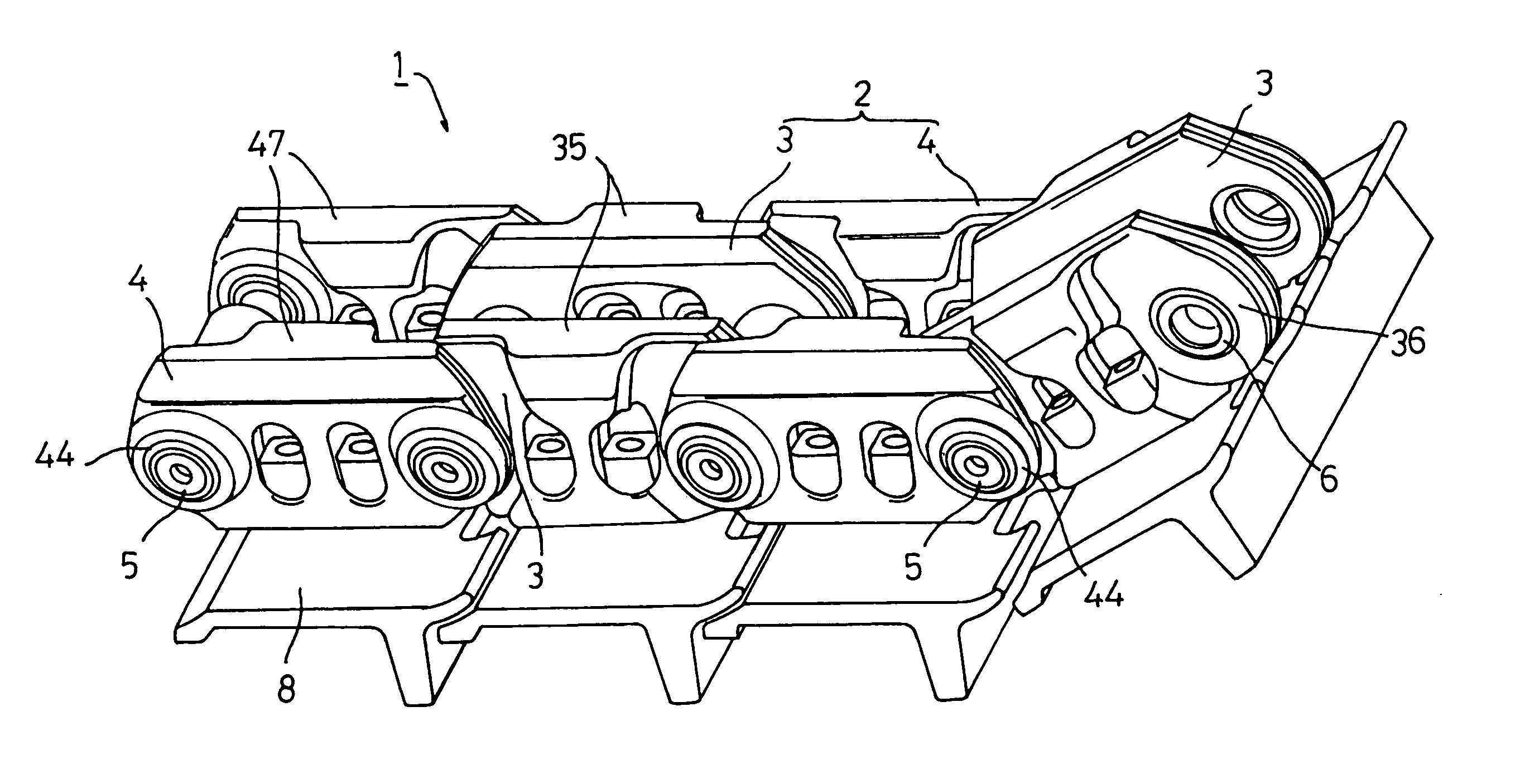
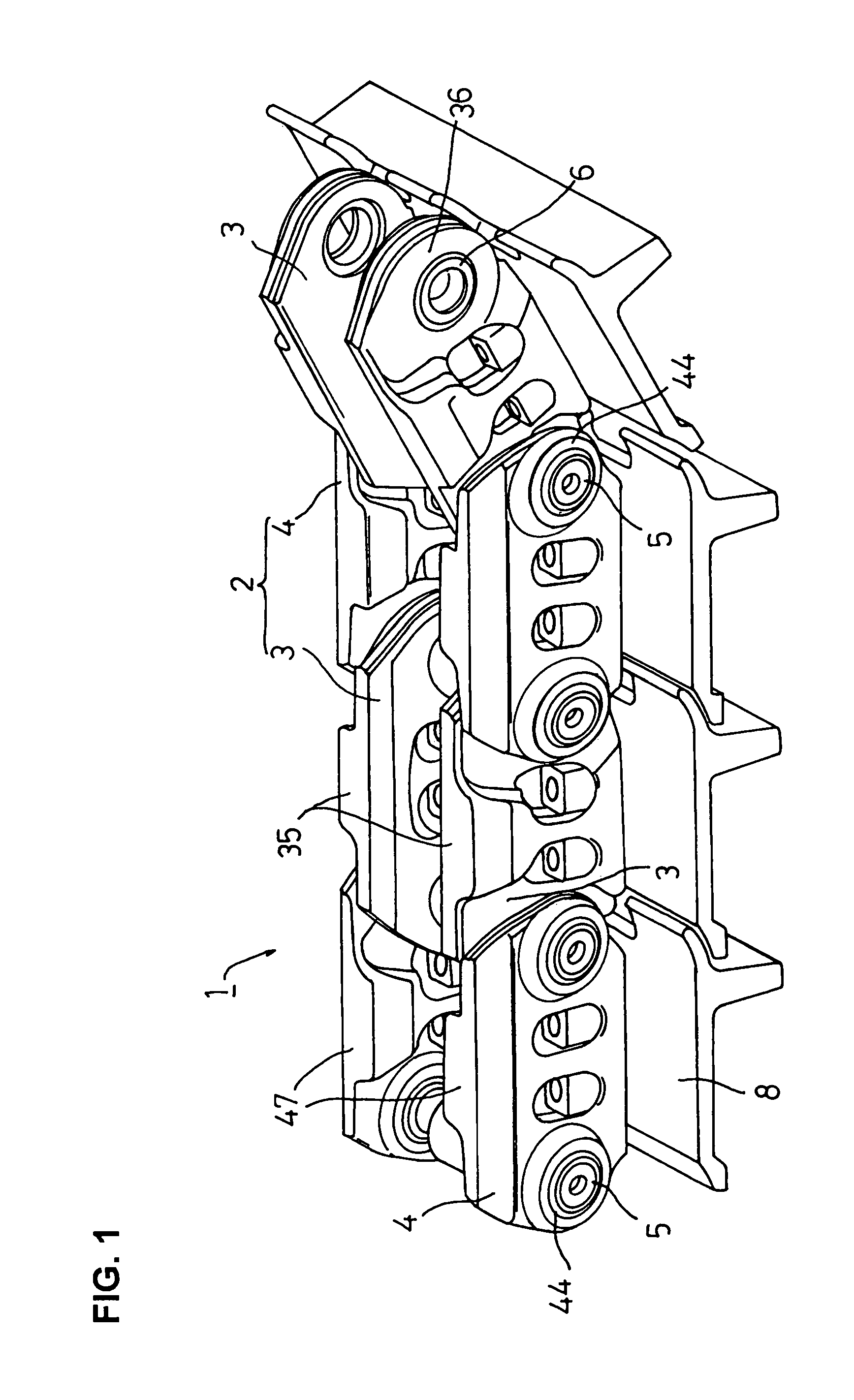
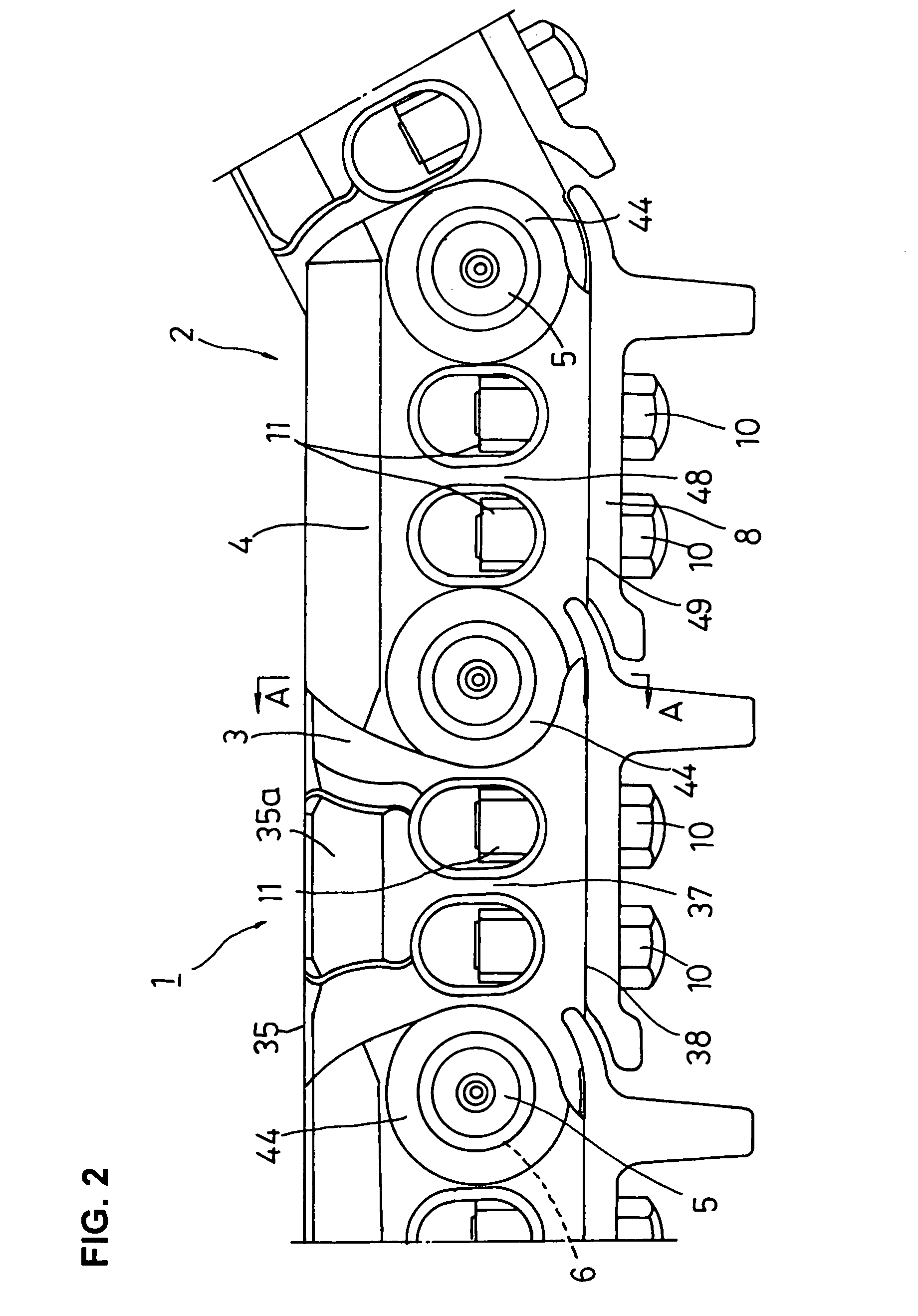
[0024]FIG. 1 is a partial perspective illustration of a track according to an embodiment of the present invention. FIG. 2 is a partial front view of the track. FIG. 3 is a top plan view showing, in cross section, a part of FIG. 2. FIG. 4 is an enlarged cross sectional view taken on the line A-A of FIG. 2. FIG. 5 is a perspective illustration of an internal link of the track. FIG. 6 is a perspective illustration of an external link of the track.

[0025]A track with a rotatable bushing 1 of the present embodiment is usually incorporated into the undercarriage (not shown) of a track-type construction machine (work machine) such as a hydraulic excavator, a bulldozer et cetera. As partially shown in FIG. 1, the track with a rotatable bushing 1 (hereinafter called the “track 1”) comprises ...


PUM

PropertyMeasurementUnit
inclination angleaaaaaaaaaa
thicknessaaaaaaaaaa
thickness dimensionaaaaaaaaaa

Abstract

In a track with a rotatable bushing which is brought into engagement with a sprocket of a track-type vehicle, it is intended that strength is enhanced rationally by link functionality sharing and by combination of such assigned functional tasks for achieving further improvements in rotatable bushing function. To this end, a first bolt insertion hole provided in a track shoe mount surface of an external link and a second bolt insertion hole provided in a track shoe mount surface of an internal link are arranged on the same straight line, and a straight line connecting the first bolt insertion hole and the second bolt insertion hole is situated at a position more interior than a contact plane of the external link and internal link.

Description

CROSS REFERENCE TO RELATED APPLICATION[0001]The present application is a Continuation-In-Part of the patent application Ser. No. 10 / 727,573, filed Dec. 5, 2003, and issued as U.S. Pat. No. 7,325,889, which claims priority to application JP-2003-019879 filed on Jan. 29, 2003 and application JP-2003-399218 filed on Nov. 28, 2003, the entire contents of which are incorporated herein by reference.TECHNICAL FIELD[0002]The present invention relates to a track for use in track-type vehicle. More particularly, this invention is directed to a track with a rotatable bushing intended for achievement of improvement in the strength of a connection part comprising a combination of an internal link and an external link.BACKGROUND ART[0003]A known track on the undercarriage of a track-type vehicle (such as a hydraulic excavator, bulldozer et cetera) comprises endlessly-coupled track links and track shoes mounted on the respective track links. The track is passed around a sprocket and an idler which...

Claims


Application Information

Patent Timeline
Patent Type & Authority Patents(United States)
IPC IPC(8): B62D55/21
CPCB62D55/21
Inventor YAMAMOTO, TEIJIMAEDA, KAZUO
Owner KOMATSU LTD
Why Eureka
Try Eureka