Pressure exchange apparatus

a technology of pressure exchange apparatus and pressure exchange chamber, which is applied in the direction of positive displacement pump components, piston pumps, etc., can solve the problems of reducing the driving pressure, affecting the transport of pure water across the membrane, and reducing energy losses, so as to reduce the amount of energy required, and the effect of small moveable mass

Active Publication Date: 2010-02-16
KUWAIT INST FOR SCI RES
View PDF11 Cites 6 Cited by
  • Summary
  • Abstract
  • Description
  • Claims
  • Application Information

AI Technical Summary

Benefits of technology

[0007]The present invention provides a new type of pressure exchange apparatus that is particularly suitable as the hydraulic energy recovery part of a high pressure reverse osmosis process for desalting sea water or saline solutions instead of a conventional reverse pump or turbine machine. The pressure exchange apparatus of the present invention is a highly efficient device by which 90% or more of the hydraulic energy contained in the pressurized exhaust fluid is transferred to the feed fluid prior to its pressurization, thus reducing the amount of energy required by the process of pressurization. Furthermore, unlike other pressure exchanger's, the pressure exchange apparatus of the present invention is characterized by having a very small moveable mass with small frictional surface area and involves no external momentum transfer to or from any other fluid streams. Therefore, the apparatus is less vulnerable to break down and / or loss of energy.

Problems solved by technology

The transport of pure water through the membrane causes an increase in the solutes' concentration in the pressurized solution to a point that the osmotic pressure becomes too high, thus causing the driving pressure, which effects the transport of pure water across the membrane, to diminish.
Due to the requirement for the inclusion of a piston-cylinder arrangement as well as valves, energy losses may be high.
Moreover, there may be practical limitations on the use of rapidly operated valves in handling large volumes of liquids.

Method used


Image

  • Pressure exchange apparatus
  • Pressure exchange apparatus
  • Pressure exchange apparatus

Examples


Embodiment Construction

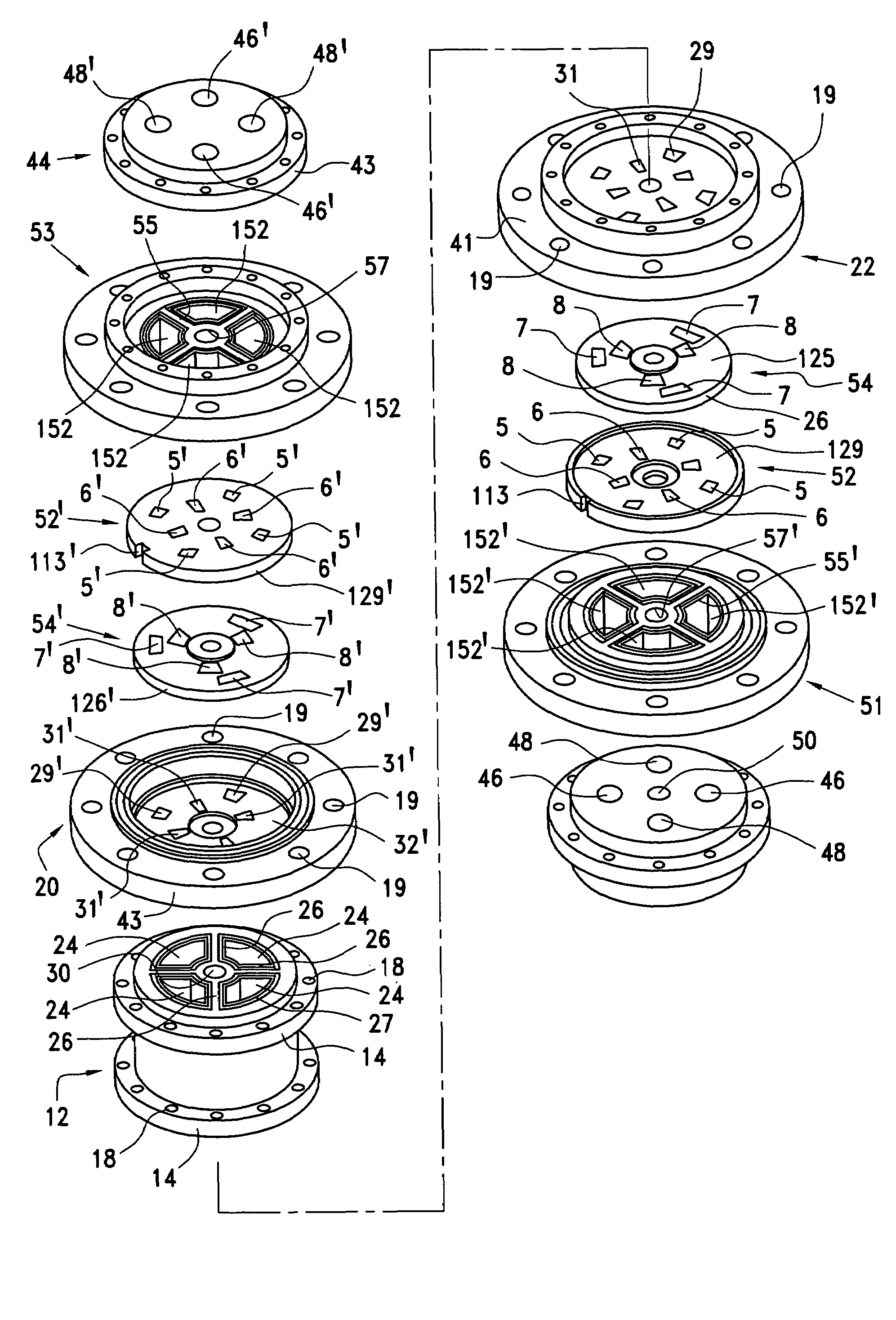
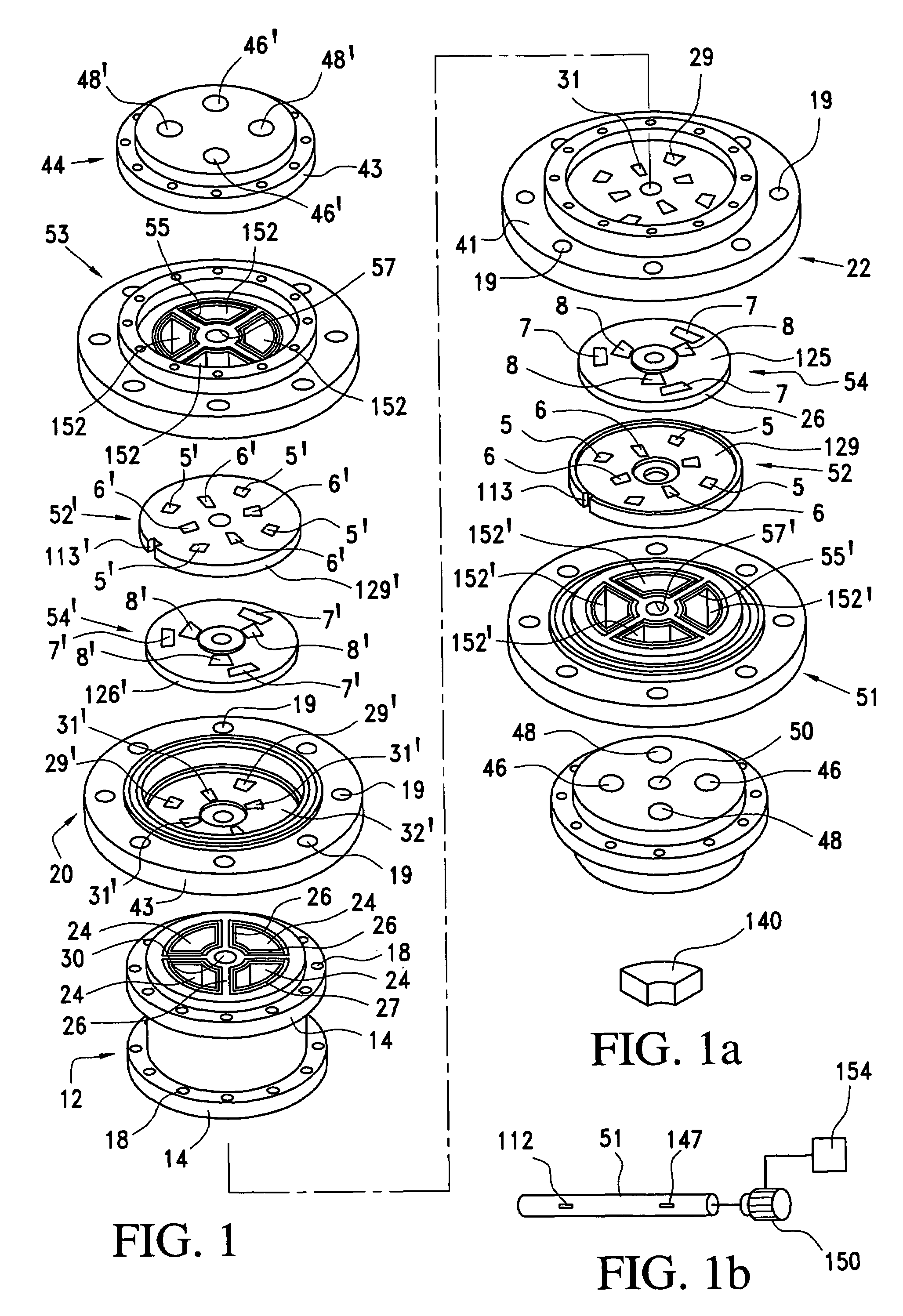
[0021]The invention will now be described in connection with the accompanying drawings wherein like reference numerals have been used to designate like parts.

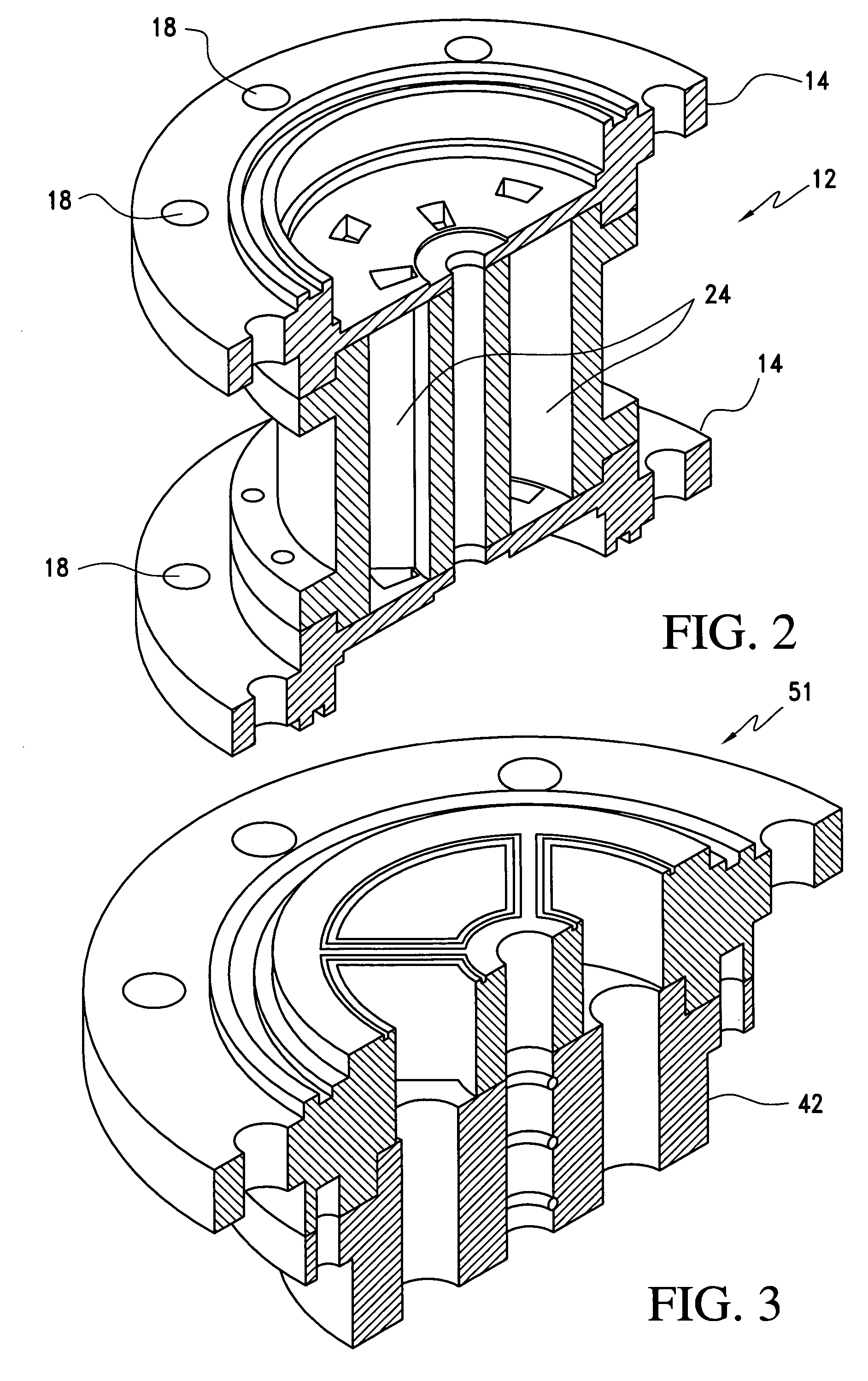
[0022]As illustrated in FIGS. 1 and 2, the pressure exchange apparatus in accordance with the present invention comprises a conduit or main section 12 having two end flanges 14. The two end flanges 14 are attached to, or preferably, an integral part of the main section 12 and are attached to a pair of dual disk holders 20, 22 by means of bolts, bolt holes 18 and internally threaded bolt holes 19.

[0023]The main section 12 also defines four longitudinally extending internal compartments or chambers 24 which have a generally pie shaped cross section and which are isolated from one another by radially extending walls or partitions 26. The main section 12 also includes a housing cylinder or central casing which defines a bearing surface or passage way 30 for receiving a shaft therein.

[0024]Four sliding blocks or pistons 40 each have...


PUM


Abstract

A pressure exchange apparatus includes a main section having a plurality of internal chambers and a piston disposed in each of the chambers. The apparatus also includes a pair of fluid distributor assemblies fixed to the main section and co-axial therewith. Each of the distributors include inlet and outlet ports for communicating with one of the internal chambers and sealingly separated from the other chambers. A pair of dual disk controller assemblies each of which includes a fixed disk and a moveable disk housed in a dual disk holder for directing fluid streams from one of the ports into and out of one of the chambers is also provided.

Description

FIELD OF THE INVENTION[0001]This invention relates to a pressure exchange apparatus for exchanging hydraulic pressure from a fluid stream at relatively high pressure to a fluid stream at relatively low pressure and more particularly to a pressure exchange apparatus for hydraulic energy recovery by directly transferring the hydraulic pressure energy contained in a pressurized exhaust fluid to a feed fluid in a process that requires pressurization.BACKGROUND FOR THE INVENTION[0002]An industrial process that requires considerable pressurization of solutions is the desalting of seawater or other relatively highly concentrated saline aqueous solutions using reverse osmosis membrane technology. In this type of process, the saline solution is pressurized, by using a mechanical or electrical driven device, to reach a pressure that exceeds the osmotic pressure of the solution, which is a function of the solutes' concentration. The excess pressure, which is equivalent to the working pressure ...

Claims


Application Information

Patent Timeline
Patent Type & Authority Patents(United States)
IPC IPC(8): F04F99/00F04B7/00F04B9/117F04B39/08
CPCF04B9/1176
Inventor EL-SAYED, ESSAM E. F.ABDEL-JAWAD, MAHMOUDAL-ODWANI, ALI
Owner KUWAIT INST FOR SCI RES
Why Eureka
Try Eureka