Jacket sleeve with grippable tabs for a cable connector

a technology of connectors and sleeves, applied in the direction of cable junctions, coupling device details, cable connection, etc., can solve the problems of cable replacement, concentric neutrals oxidizing and corroding, and affecting so as to facilitate the service life of cables, improve the grip of sleeves, and reduce slippag

Active Publication Date: 2010-02-16
EATON INTELLIGENT POWER LTD
View PDF248 Cites 30 Cited by
  • Summary
  • Abstract
  • Description
  • Claims
  • Application Information

AI Technical Summary

Benefits of technology

[0012]A jacket sleeve with grippable tabs provides protection to exposed portions of cable that are connected to an electrical connection. The jacket sleeve can be made as part of the electrical connector or may be connected subsequent to its creation through the use of glues or other adhesives. The jacket sleeve can be made of a material that is more pliable than the electrical connector, making it easier for a lineperson to place the sleeve over an exposed portion of cable. The jacket sleeve can also include holes or slots either in the sleeve or in tabs that are attached to the sleeve. A lineperson can place one or more fingers, which may include the thumb, into each hole or slot in order to get a better grip on the sleeve and pull the sleeve over the exposed portion of cable with less slippage and less effort on the part of the lineperson.
[0017]For another aspect of the present invention, a method of making an electrical connector can include molding a connector body having the features described hereinabove. The connector body may be allowed to cure and can then be placed into a second mold. In the second mold, a jacket sleeve having the features described hereinabove can be overmolded onto the connector body. The overmolded material cures and cross-links with the connector body creating a strong, permanent chemical bond.

Problems solved by technology

The concentric neutrals are particularly at risk and tend to decay rapidly when exposed to moisture.
Moisture causes the concentric neutrals to oxidize and corrode.
After a certain level of corrosion has built up, the cable needs to be replaced because the return path for the electrons has been permanently disrupted.
While the exposed portions of the cable are at risk for decay and damage due to exposure to water and other elements, unexposed portions of the cable are also at risk.
For example, water that reaches and contacts the concentric neutrals of the exposed portion of the cable can be wicked away from the point of contact to other areas miles away from the exposed portion of the cable, causing corrosion and failure of the concentric neutrals along long sections of cable.
When completing the attachment of several connectors to cables, the multiple steps of pulling the sleeve down onto the cable and then pulling it back up the cable once the elbow connector was attached greatly increased the time and effort needed to properly protect the cable.
Unfortunately, the combination jacket sleeve and elbow connector has several drawbacks.
One side effect of adding carbon black to rubber is that it makes the rubber extremely stiff.
The stiffer jacket sleeve is difficult to get over the exposed portion of the cable, once mastic and / or tape has been applied because the sleeve does not stretch well but still must have an interference fit with the tape or mastic covering the exposed portion of the cable.
Another problem with the combination jacket sleeve and elbow connector is that the small tabs provided along the edge of the jacket sleeve are not sufficient to assist in grasping and pulling the jacket sleeve over the tape and mastic.
As a function of the application, a lineperson frequently gets grease on their hands, making it difficult to grasp and hold onto the small tabs provided on the jacket sleeve.
Yet another problem with the combination jacket sleeve and elbow connector is that, the window for error in building up the protective layers of tape and mastic on the exposed portion of the cable is substantially less with the stiffer material being used for the jacket sleeve.
Unfortunately, mastic tends to become loose and runny under extreme heat and comes off of the cable if it is not held in place.
However, the stiffer the sleeve is, the less a lineperson will be able to get the sleeve over tape that has a diameter that is a little too large.

Method used


Image

  • Jacket sleeve with grippable tabs for a cable connector
  • Jacket sleeve with grippable tabs for a cable connector
  • Jacket sleeve with grippable tabs for a cable connector

Examples


Embodiment Construction

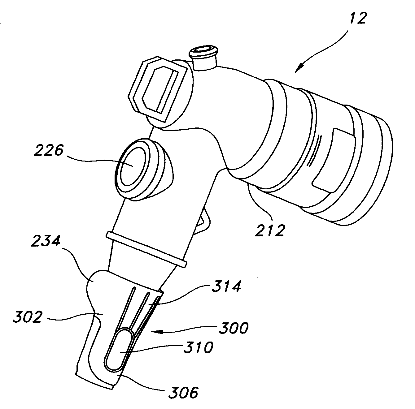
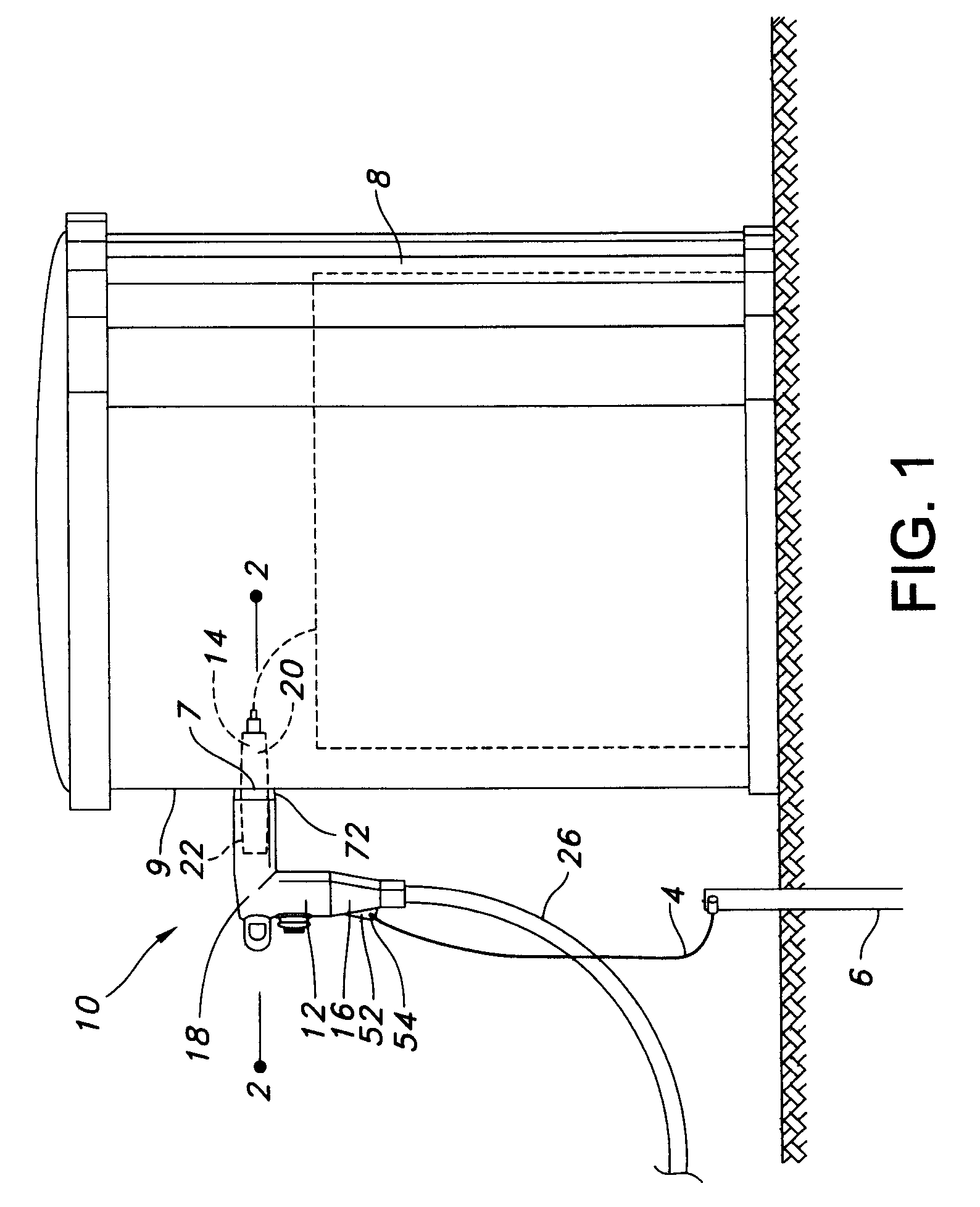
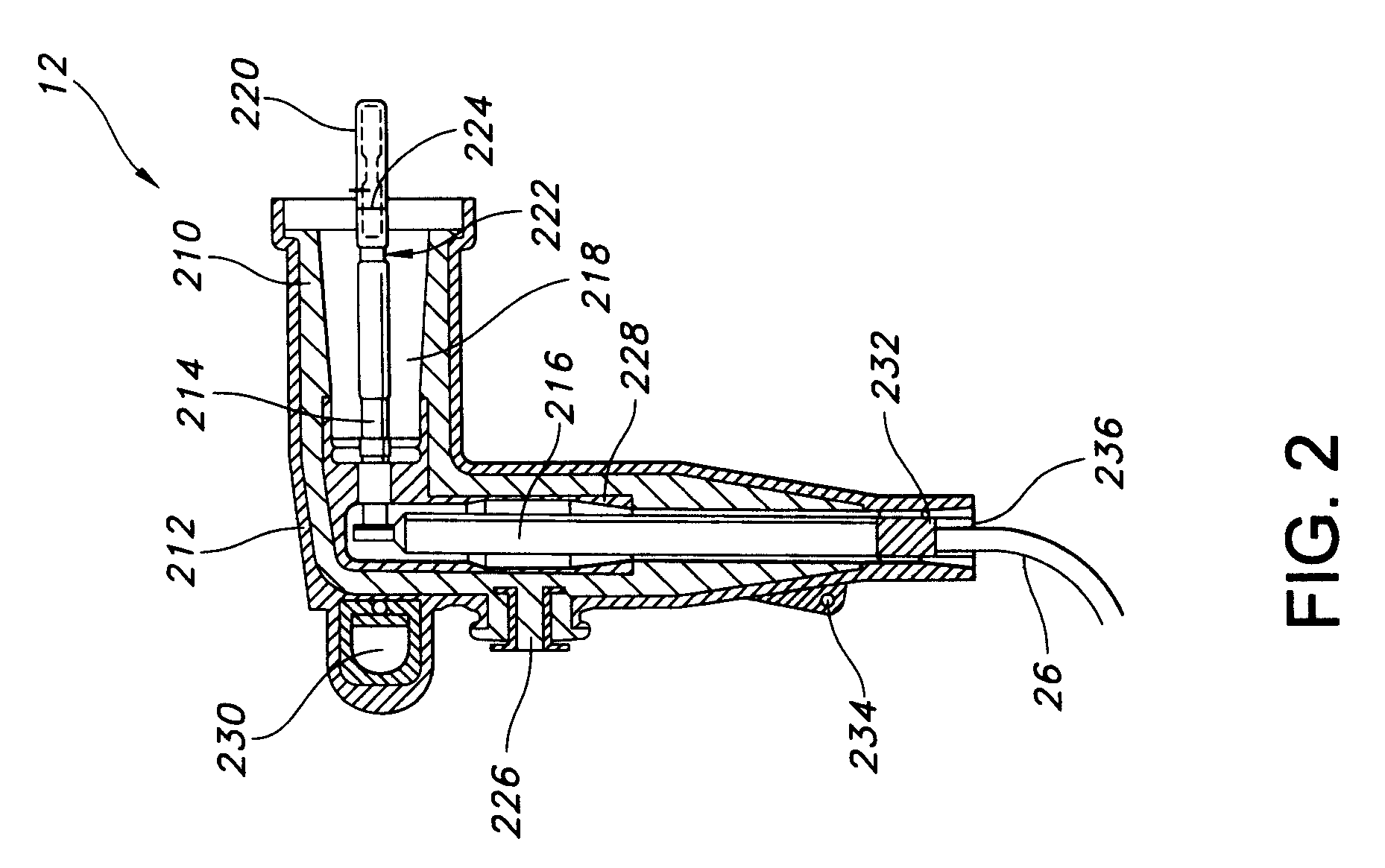
[0026]The present invention is directed to a jacket sleeve for an electrical connector and methods for making the same. Exemplary embodiments of the invention can be more readily understood by reference to the accompanying figures.

[0027]Exemplary embodiments of the present invention include a jacket sleeve for receiving therethrough and protecting a high voltage cable in a power distribution environment. However, it should be apparent that there could be many different ways of implementing the invention in an electrical environment, and the invention should not be construed as limited to a high voltage environment or any one set of features or methods described herein. The inventive functionality of the jacket sleeve with grippable tabs will be explained in more detail in the following description and is disclosed in conjunction with the remaining figures.

[0028]Referring now to the drawings in which like numerals represent like elements throughout the several figures, aspects of the...


PUM

PropertyMeasurementUnit
longitudinal lengthaaaaaaaaaa
conductiveaaaaaaaaaa
oval shapeaaaaaaaaaa

Abstract

A jacket sleeve with grippable tabs provides protection to exposed portions of cable that are connected to an electrical connection. The jacket sleeve can be made as part of the electrical connector or may be connected subsequent to its creation through the use of glues or other adhesives. The jacket sleeve can be made of a material that is more pliable than the electrical connector, making it easier for a lineperson to place the sleeve over an exposed portion of cable. The jacket sleeve can include holes or slots either in the sleeve or in tabs that are attached to the sleeve. A lineperson can place one or more fingers into each hole or slot in order to get a better grip on the sleeve and pull the sleeve over the exposed portion of cable with less slippage and effort on the part of the lineperson.

Description

FIELD OF THE INVENTION[0001]The present invention relates generally to the field of power distribution equipment. More particularly, the invention relates to jacket sleeves used with cable and connectors for power distribution equipment.BACKGROUND OF THE INVENTION[0002]Separable connectors are typically employed to interconnect sources of energy, such as electrical distribution network conductors, to localized distribution components, such as switchgears and transformers. These connectors, for example, typically include a bushing insert, which is mounted in the bushing well of the switchgear, and an elbow connector which is releasably connected to the bushing insert on one end and a distribution conductor, such as a high voltage cable, of the network circuit feeding the switchgear. When the elbow is interconnected to the bushing, the switchgear is thus interconnected into the distribution network and thereby energized. Likewise, if the elbow is removed, the switchgear is disconnecte...

Claims


Application Information

Patent Timeline
Patent Type & Authority Patents(United States)
IPC IPC(8): H01R13/56
CPCH01R13/53H01R13/6335Y10T29/49117Y10T29/49208
Inventor HUGHES, DAVID CHARLESMAKAL, JOHN MITCHELLGEBHARD, SR., MICHAEL JOHNROSCIZEWSKI, PAUL MICHAEL
Owner EATON INTELLIGENT POWER LTD
Why Eureka
Try Eureka