
Metal scrap submergence apparatus

a submergence apparatus and metal scrap technology, applied in the direction of furnaces, charge manipulation, material recovery, etc., can solve the problems of high oxidation loss, difficult melting of thin walled scrap pieces, and rapid submergence in molten metal

Active Publication Date: 2010-02-16
PYROTECK INC
View PDF10 Cites 3 Cited by
  • Summary
  • Abstract
  • Description
  • Claims
  • Application Information

AI Technical Summary

Benefits of technology

The patent describes a device that can hold and submerge material scraps. It is made of heat-resistant or refractory material and has a chamber for holding the scraps. The device can also have rods that are inserted into passages in the body. Additionally, there is a gas injection inlet. The technical effect of this device is to provide a way to safely and efficiently handle material scraps during manufacturing processes.

Problems solved by technology

Melting thin walled scrap pieces is difficult because rapid submergence in molten metal is severely hampered since thin walled scrap pieces tend to float on molten metal.
Unfortunately, extended exposure to the hostile atmosphere in a traditional melting furnace results in extremely high oxidation loss.
In addition, the forces created by the high speed metal circulation impart stresses on the chamber walls.
Since the chamber is often an integral component of the furnace, repair of the walls, or in fact even cleaning, can be a difficult and expensive undertaking, particularly in the form of furnace downtime.

Method used


Image

  • Metal scrap submergence apparatus
  • Metal scrap submergence apparatus
  • Metal scrap submergence apparatus

Examples


Embodiment Construction

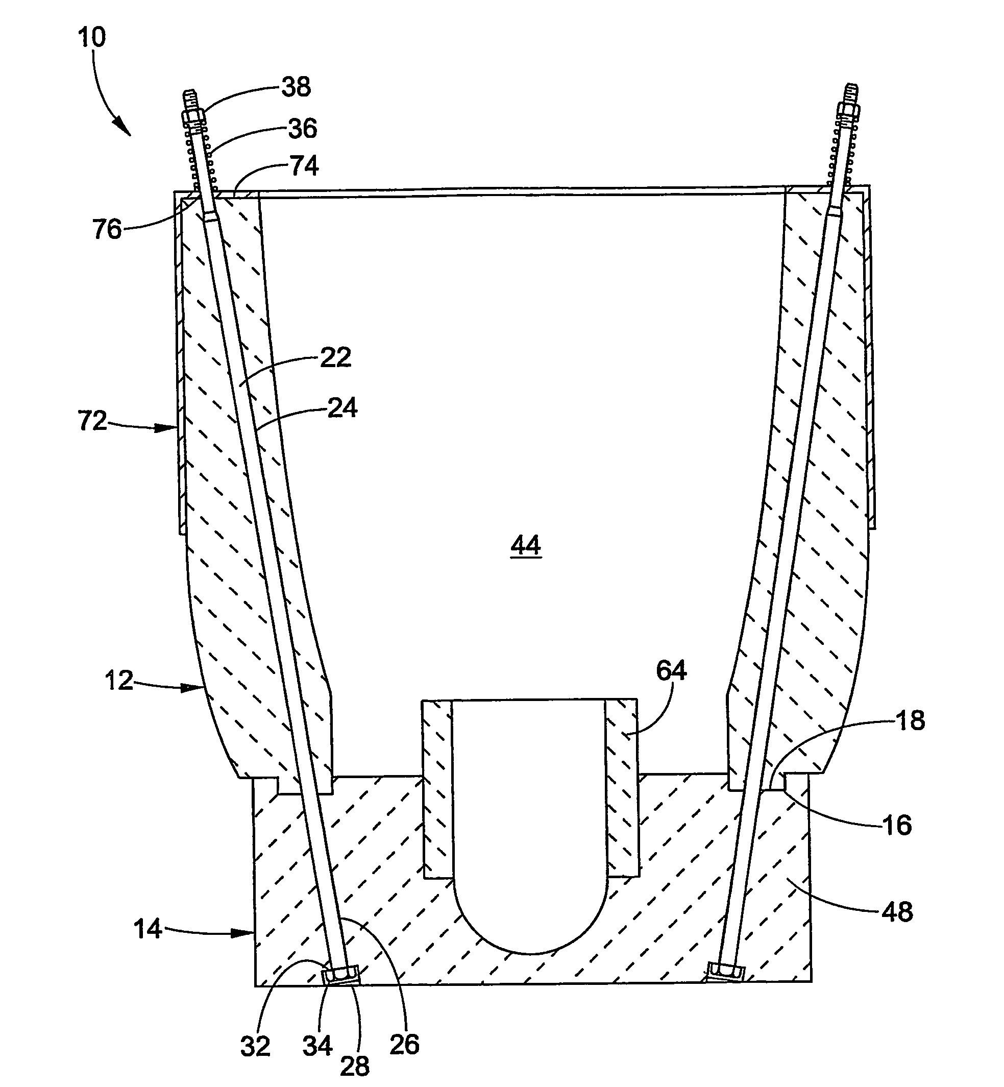
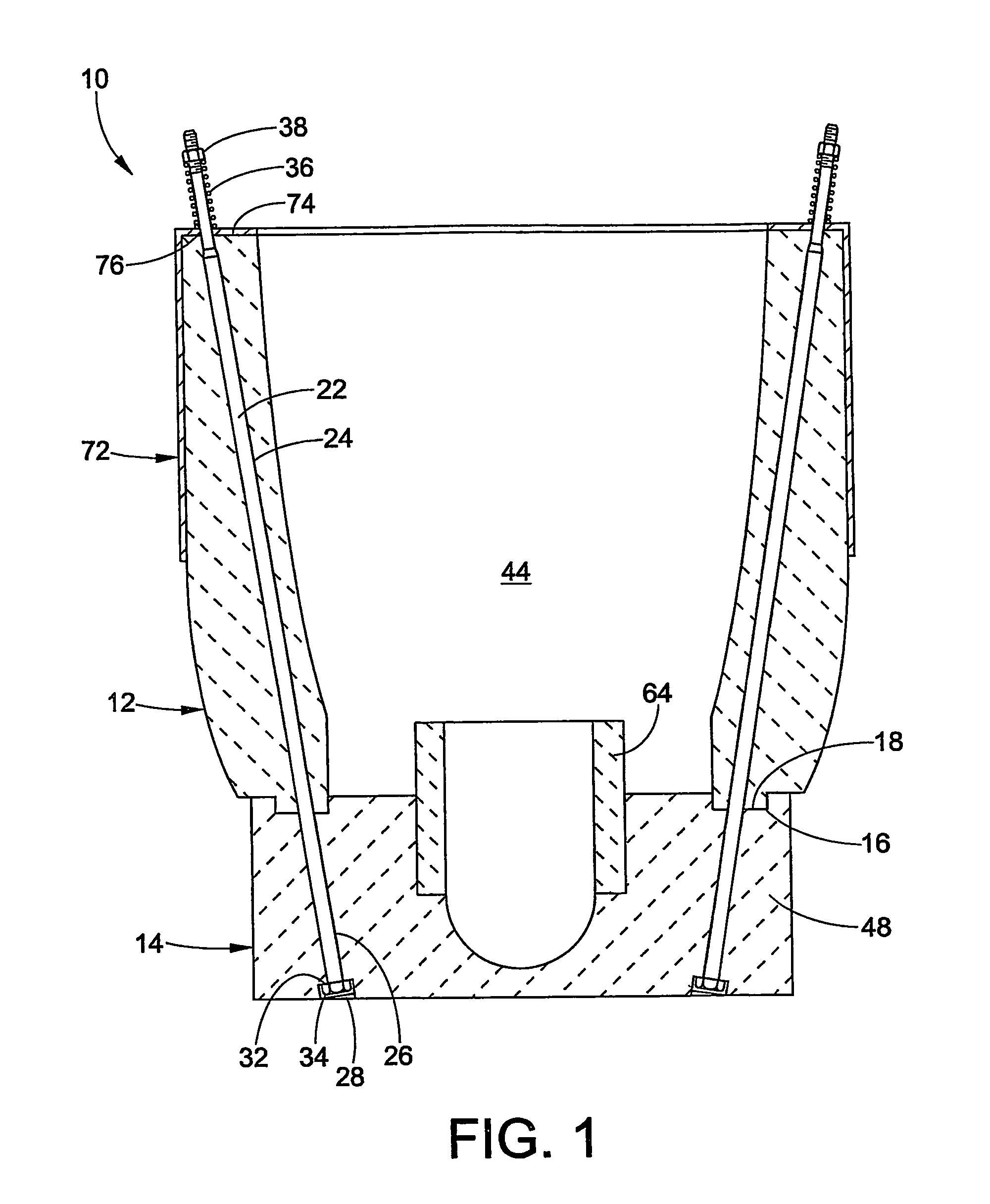
[0018]With reference to FIG. 1, a modular metal scrap submergence device 10 includes a side wall 12 mounted to a separate base 14. The side wall and the base are made from a refractory material, one non-limiting example being graphite. In the embodiment depicted in FIG. 1, the base 14 includes a notch 16 that receives a cooperative protrusion 18 of the side wall 12. In an alternative embodiment, the base can include a protrusion and the side wall can include an appropriately shaped notch or channel for receiving the protrusion. In yet another alternative embodiment, a metal scrap submergence device 10 includes a body of refractory material having a side wall 12 and a base 14. In this instance, the side wall 12 and the base 14 are not removable from one another. The scrap submergence device is not limited to simply the embodiments depicted, but can include submergence devices disclosed in U.S. Pat. Nos. 6,217,823; 6,036,745 and 4,286,985, each of which is herein incorporated by refer...


PUM

PropertyMeasurementUnit
tensionaaaaaaaaaa
compressive forceaaaaaaaaaa
heightaaaaaaaaaa

Abstract

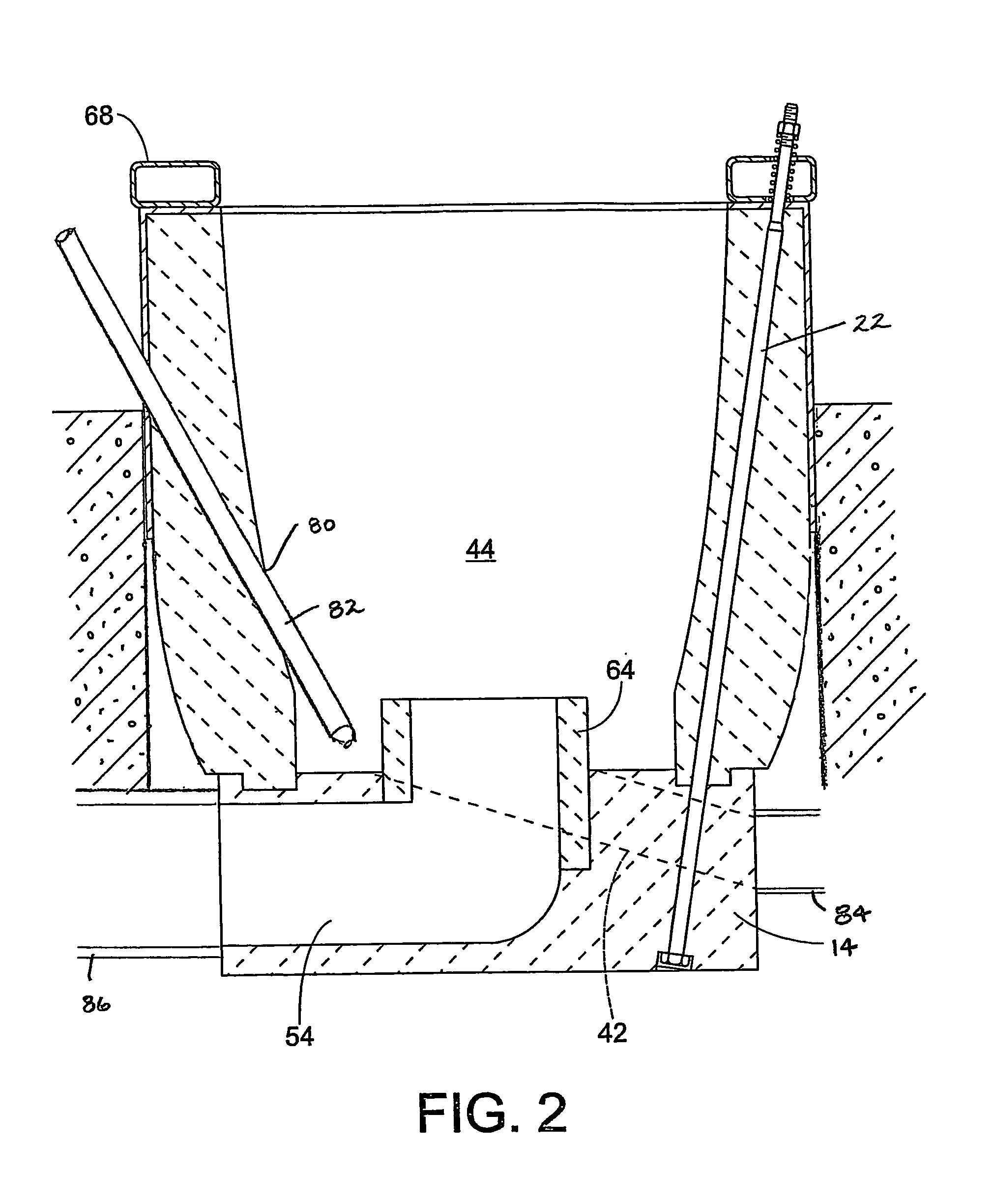
A material scrap submergence device comprises a body (10) of heat resistant and / or a refractory material that includes a side wall (12) and a base (14) that define a submergence chamber (10). The refractory body (10) can include passages (24) that receive rods (22). The rods (22) can place the refractory body (10) under compression. In another embodiment, the body is confined by a frame (72) attached to the body. The submergence chamber (10) can also be used as a gas injection chamber.

Description

[0001]This application claims the benefit of provisional application No. 60 / 525,534 filed Nov. 26, 2003, which is herein incorporated by reference.BACKGROUND OF THE INVENTION[0002]In the recycling of metals, aluminum scrap pieces are melted for treatment and processing. A large portion of the aluminum scrap pieces are thin walled as a result of the mechanical shaping action from which they were formed. Melting thin walled scrap pieces is difficult because rapid submergence in molten metal is severely hampered since thin walled scrap pieces tend to float on molten metal. Unfortunately, extended exposure to the hostile atmosphere in a traditional melting furnace results in extremely high oxidation loss.[0003]In a typical melting operation, a melting furnace is provided with an enclosed hearth and a connected open sidewell. Usually the sidewell is divided into a pump well and a melting bay. A pump or other molten metal flow inducing apparatus is positioned in the pump well and pumps mo...

Claims


Application Information

Patent Timeline
Patent Type & Authority Patents(United States)
IPC IPC(8): C21B13/00C22B21/00F27D1/00F27D3/00F27D3/12F27D27/00
CPCC22B21/0069C22B21/0092F27D1/004F27D3/0025F27D3/12F27D27/00F27D3/0033F27D3/0031Y02P10/218F27D2001/0079Y10S266/901Y02P10/20
Inventor VILD, CHRIS T.VAN LINDEN, JAN H. L.
Owner PYROTECK INC
Learn More