Method and apparatus for adaptively controlling antenna parameters to enhance efficiency and maintain antenna size compactness

a technology of adaptive control and antenna parameters, applied in the direction of resonant antennas, substantially flat resonant elements, substation equipment, etc., can solve the problems of insufficient space for conventional quarter and half wavelength antenna elements, large antennas, and inability to meet the needs of certain communications devices,

Inactive Publication Date: 2010-02-16
SKYCROSS INC
View PDF42 Cites 65 Cited by
  • Summary
  • Abstract
  • Description
  • Claims
  • Application Information

AI Technical Summary

Problems solved by technology

The resulting larger antenna, even at a quarter wavelength, may not be suitable for use with certain communications devices, especially portable and personal communications devices intended to be carried by a user.
Since these antennas tend to be larger than the communications device, they are typically mounted with a portion of the antenna protruding from the communications device and thus are susceptible to breakage
Smaller packaging of state-of-the-art communications devices, such as personal handsets, does not provide sufficient space for the conventional quarter and half wavelength antenna elements.
It is generally not considered feasible to utilize a single antenna for each operational frequency or to include multiple matching circuits to provide proper resonant frequency operation from a single antenna.
Currently, designers struggle to obtain adequate multi-band antenna performance for the multi-band features of the devices.
But as is known, efficiency and bandwidth are related and a design trade-off is therefore required.
Designers can optimize performance in one (or in some cases more than one) operating frequency band, but usually must compromises the efficiency or bandwidth to achieve adequate performance in two or more bands simultaneously.
However, most portable communications devices seldom require operation in more than one band at any given time.
Poor power amplifier (PA) efficiency due to impedance matching of the antenna and the power amplifier only for maximum power output, without considering PA output impedance changes as a function of the PA's output power level.B.
Poor PA efficiency due to poor antenna / PA impedance matching over multiple frequency bands or within a band, due primarily to the antenna's relatively narrow bandwidth resulting from, according to the Chu-Harrington limitation, the relatively small antenna volume.
Poor PA efficiency due to poor antenna / PA impedance matching over multiple frequency bands or within band resulting from hand-effect or proximity effect detuning of the antenna resonant frequency.D.
Loss of radiative energy transfer (coupling inefficiency) due to poor antenna / PA impedance matching resulting from antenna bandwidth limitations due to the use of a relatively small antenna in the communications device, which, according to the Chu-Harrington relation, has a relatively narrow bandwidth.E.
Loss of radiative energy transfer (coupling efficiency) due to detuning of the antenna resonant frequency caused by the hand-effect or proximity effect.

Method used


Image

  • Method and apparatus for adaptively controlling antenna parameters to enhance efficiency and maintain antenna size compactness
  • Method and apparatus for adaptively controlling antenna parameters to enhance efficiency and maintain antenna size compactness
  • Method and apparatus for adaptively controlling antenna parameters to enhance efficiency and maintain antenna size compactness

Examples


Embodiment Construction

[0037]Before describing in detail the particular method and apparatus related to controlling antenna structures and operating parameters, it should be observed that the present invention resides primarily in a novel and non-obvious combination of elements and process steps. So as not to obscure the disclosure with details that will be readily apparent to those skilled in the art, certain conventional elements and steps have been presented with lesser detail, while the drawings and the specification describe in greater detail other elements and steps pertinent to understanding the invention.

[0038]The following embodiments are not intended to define limits as to the structure or method of the invention, but only to provide exemplary constructions. The embodiments are permissive rather than mandatory and illustrative rather than exhaustive.

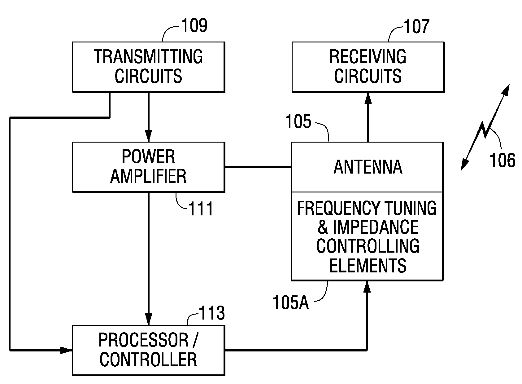
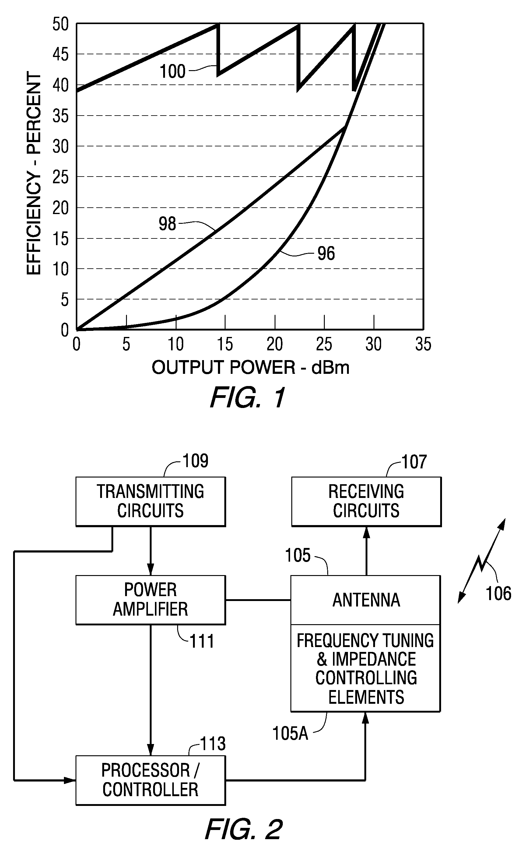
[0039]According to one embodiment of the present invention, the antenna is retuned (by controlling its effective electrical length) to a desired res...


PUM


Abstract

An antenna for a communications device having configurable elements controlled to modify an antenna impedance and / or an antenna resonant frequency to improve performance of the communications device. The antenna impedance is controlled to substantially match to an output impedance of a power amplifier that supplies the antenna with a signal for transmission. The antenna resonant frequency is controlled to overcome the effects of various operating conditions that can detune the antenna or in response to an operable frequency band.

Description

[0001]This application claims the benefit of U.S. Provisional Patent Application No. 60 / 619,231 filed on Oct. 15, 2004.FIELD OF THE INVENTION[0002]The present invention is related generally to antennas for wireless communications devices and specifically to methods and apparatuses for adaptively controlling antenna parameters to improve performance of the communications device.BACKGROUND OF THE INVENTION[0003]It is known that antenna performance is dependent upon the size, shape and material composition of the antenna elements, the interaction between elements and the relationship between certain antenna physical parameters (e.g., length for a linear antenna and diameter for a loop antenna) and the wavelength of the signal received or transmitted by the antenna. These physical and electrical characteristics determine several antenna operational parameters, including input impedance, gain, directivity, signal polarization, resonant frequency, bandwidth and radiation pattern.[0004]Gen...

Claims


Application Information

Patent Timeline
Patent Type & Authority Patents(United States)
IPC IPC(8): H01Q1/24H01Q1/50
CPCH01Q1/243H01Q9/045
Inventor CAIMI, FRANK M.O'NEILL, JR., GREGORY A.JO, YOUNG-MIN
Owner SKYCROSS INC
Why Eureka
Try Eureka