Interpolation image compression

a compression and image technology, applied in the field of compression of images, can solve the problems of degrading image quality and/or reducing the efficiency of compression, and achieve the effects of improving compression quality, reducing compression efficiency, and facilitating compression implementation

Active Publication Date: 2010-02-16
AMIMON
View PDF16 Cites 15 Cited by
  • Summary
  • Abstract
  • Description
  • Claims
  • Application Information

AI Technical Summary

Benefits of technology

[0010]In some embodiments of the invention, the encoding is performed in a lossy manner. The compression is performed in a manner which prevents lossy values from propagating throughout the image, decreasing the efficiency of the compression and / or degrading the image quality.
[0012]In accordance with some embodiments of the present invention it was determined that using non-adjacent prediction pixels for lossless and / or bounded compression methods allows easier implementation of the compression with parallel hardware, while not substantially degrading the compression quality relative to compression methods using predictors based on neighboring pixels, at least for some image types. In fact, for some test images, a better compression is possibly achieved using non-neighboring interpolation relative to neighboring interpolation.
[0013]In some embodiments of the invention, only two prediction pixels are used to determine at least some (e.g., at least 30%, 50% or even 70%) of the predictors. The use of only two prediction pixels for at least some of the encoded pixels, can reduce the complexity of the compression and decompression. In some embodiments of the invention, at least 20%, 30% or even 50% of the pixels of the image are encoded using only two predictor pixels.
[0014]In some embodiments of the invention, the differences between the actual values and the predictors are encoded using a number of bits which depends on the specific value of the difference. The encoding of the differences is optionally performed using a Huffman type code (e.g., a Golomb code). Using a varying number of bits to encode the differences allows using fewer bits for frequent difference values and more bits for rare difference values, such that a good compression can be achieved even for a lossless or bounded compression type.
[0020]Optionally, the image is divided into blocks and the recursive interpolation for calculating the predictors is performed from the edges of the block, for example from the lowest right pixel of the block on one hand and the pixels of a neighboring block to the left and above the current block. The blocks optionally have a rectangular shape. In some embodiments of the invention, the blocks include less than 50 pixels or even less than 40 pixels, in order to reduce the memory required for storing a block. Optionally, the blocks have at least one dimension greater than 4 pixels or even greater than 6 pixels. In some embodiments of the invention, the blocks comprise 4×8 pixels.
[0026]An aspect of some embodiments of the invention relates to an image compression method which encodes prediction errors that separately handles different portions of a compressed image, substantially without dependence of the parameters of the compression (e.g., encoding) in one stream on values of the other stream. In some embodiments of the invention, based on the independence of the compression of different portions of the image, separate hardware units are used to compress and / or decompress the image portions in parallel. Alternatively or additionally, the independence of the compression of the different image portions is used in pipelining the compression. While the separation into portions reduces the efficiency of the compression to a small extent, the advantage in achieving hardware parallelism in some embodiments of the invention, is considered to outweigh the reduction in efficiency.

Problems solved by technology

The compression is performed in a manner which prevents lossy values from propagating throughout the image, decreasing the efficiency of the compression and / or degrading the image quality.

Method used


Image

  • Interpolation image compression
  • Interpolation image compression
  • Interpolation image compression

Examples


Embodiment Construction

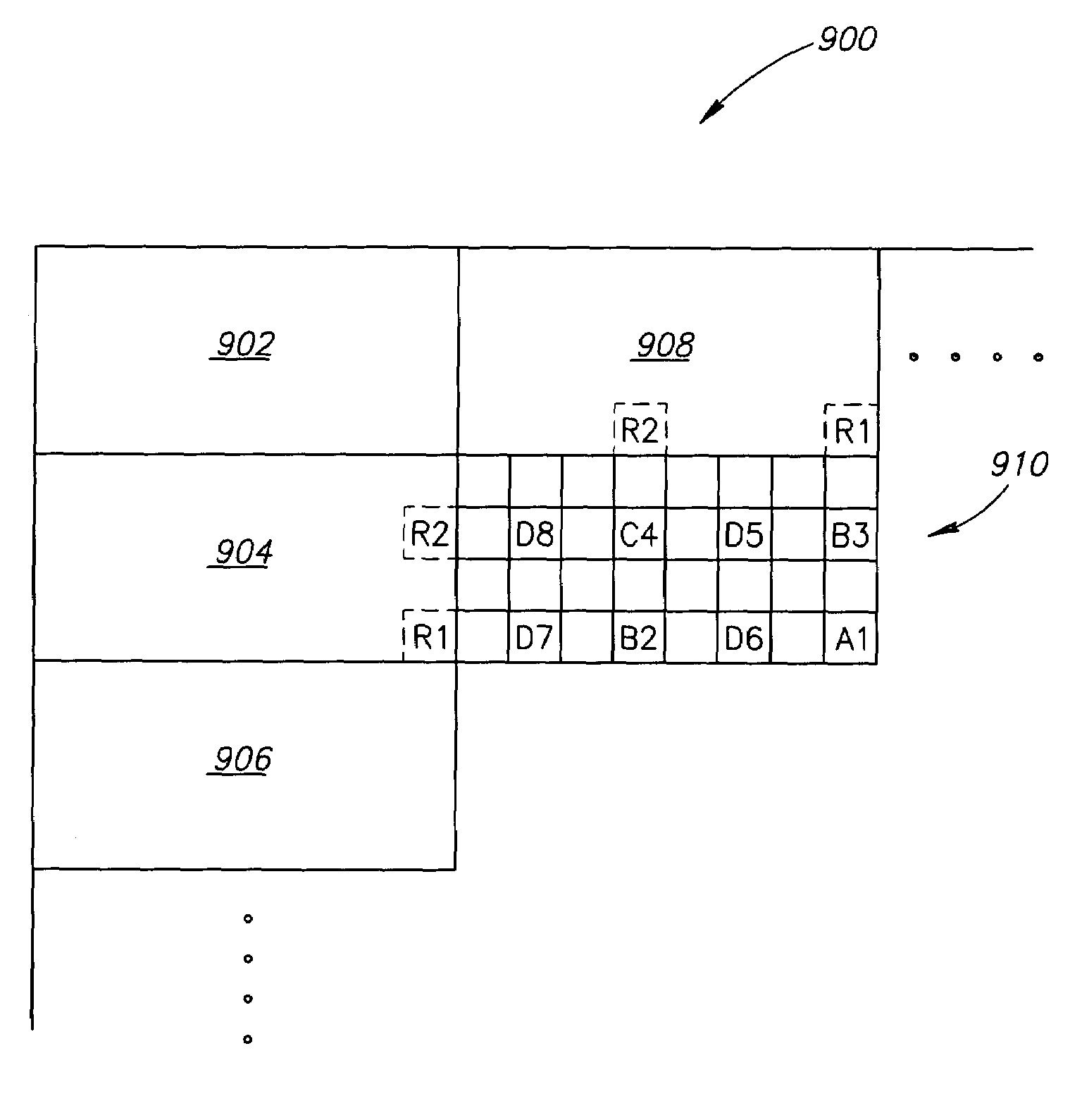
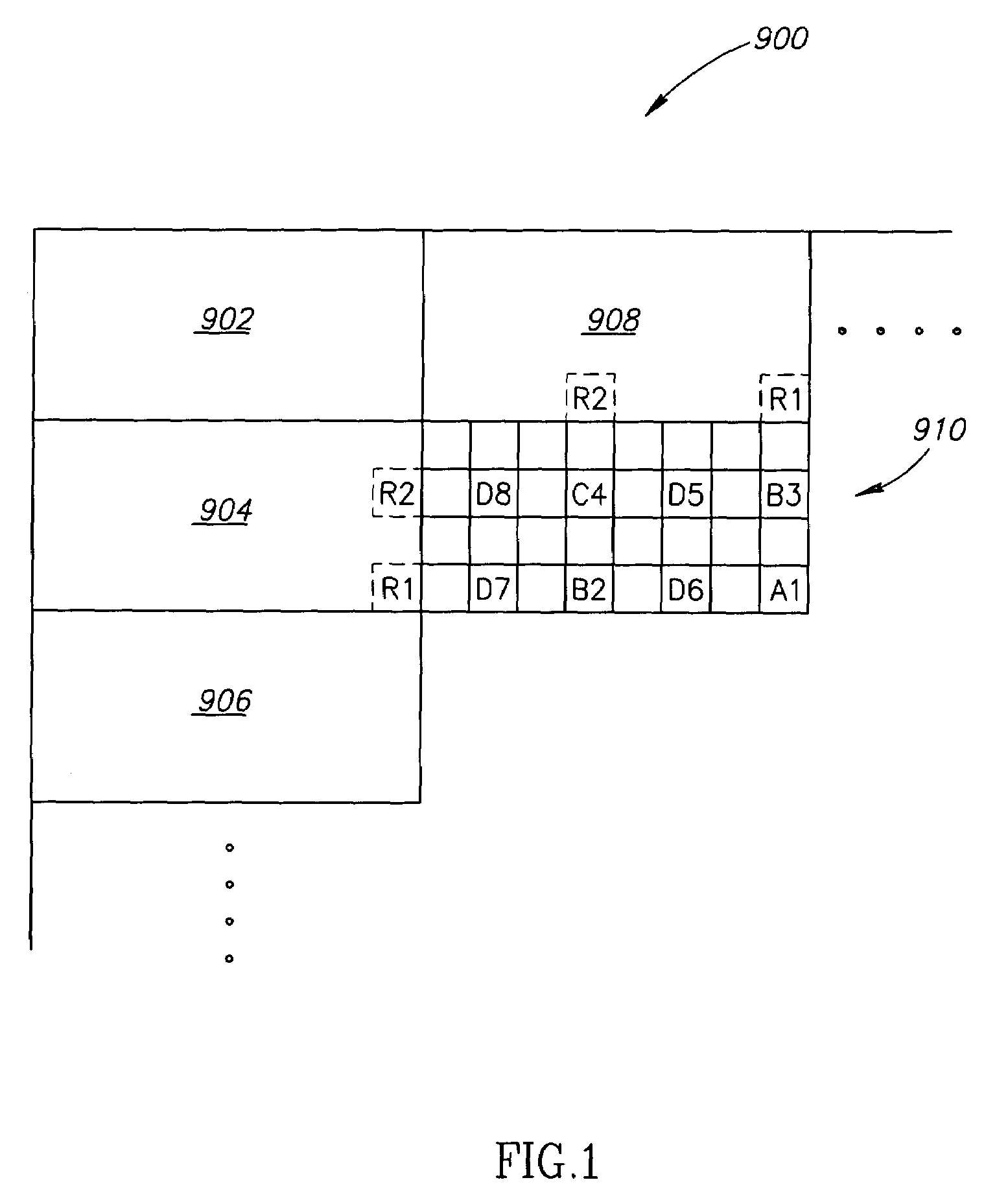
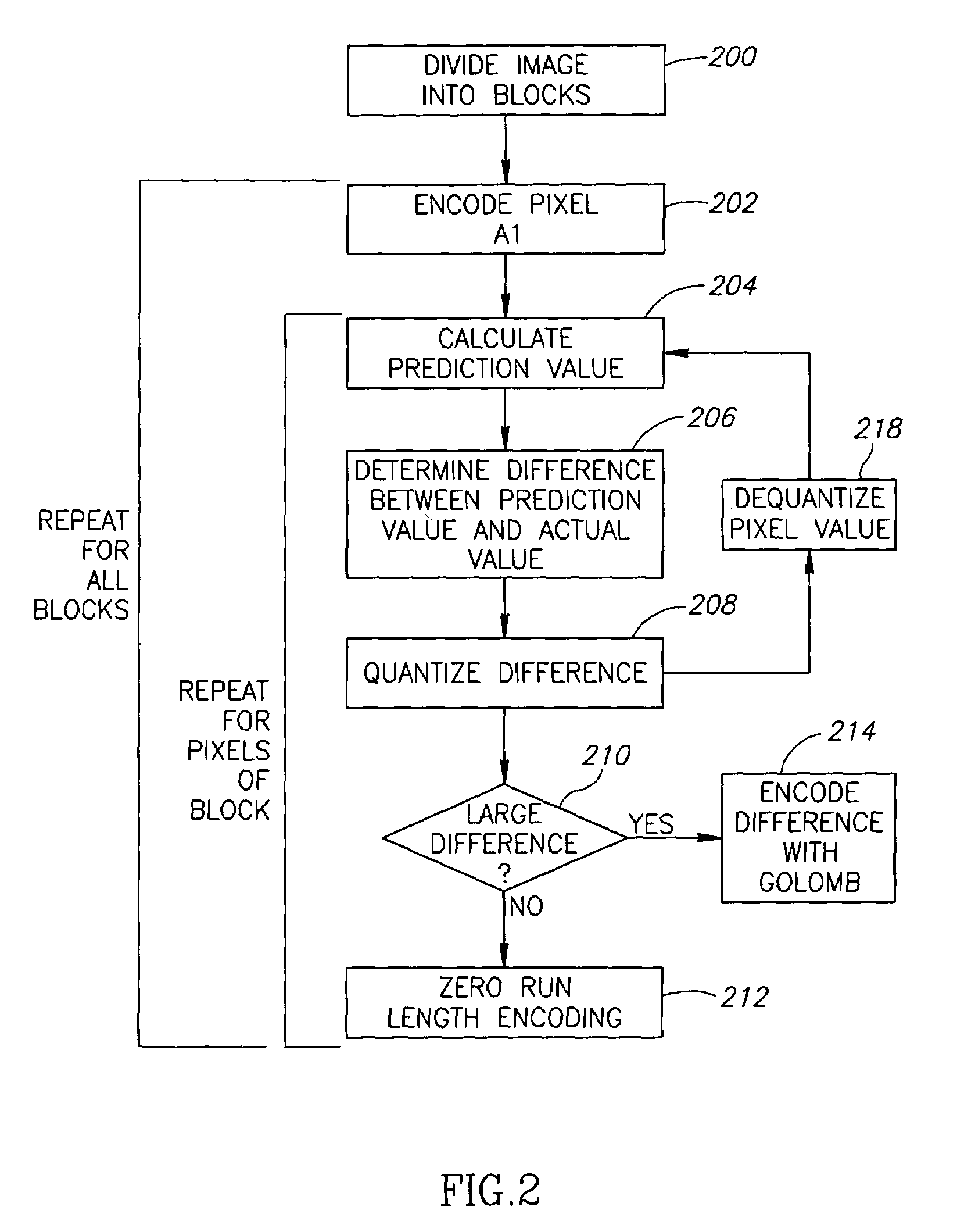
[0119]FIG. 1 is a schematic illustration of an order of compression of pixels of an image 900, in accordance with an exemplary embodiment of the invention. FIG. 2 is a flowchart of acts performed in compressing an image, in accordance with an exemplary embodiment of the invention.

[0120]The image is divided (200) into a plurality of equal size blocks (e.g., 4×8 pixel blocks). In FIG. 1, for simplicity, only blocks 902, 904, 906, 908 and 910 are shown. The left end and / or top edge blocks (e.g., 902, 904, 906 and 908) are encoded using any method known in the art. In an exemplary embodiment of the invention, the left end and top edge blocks are encoded using the method used for the other blocks using a virtual frame of the image in calculating the prediction values. The virtual frame is optionally given zero values, same values as their neighboring pixels or any other values used in the art for virtual values.

[0121]For each non-edge block (e.g., block 910), the lowest right pixel (mark...


PUM


Abstract

A method of compressing an image formed of pixels. The method includes providing a pixel of the image, to be encoded, selecting at least two pixels of the image, other than the encoded pixel, defining a straight line including the encoded pixel, to serve as prediction pixels, calculating a prediction value for the encoded pixel using at least the selected pixels, determining a difference between the calculated prediction value and the actual value of the encoded pixel, encoding the determined difference, such that the encoding error is bounded; and repeating for at least 5% of the pixels of the image.

Description

RELATED APPLICATIONS[0001]The present application claims the benefit under 119(e) from U.S. provisional application 60 / 590,197, filed Jul. 21, 2004, and U.S. provisional application 60 / 667,366, filed Mar. 31, 2005, the disclosures of which are incorporated herein by reference. The present application is also a continuation in part (CIP) of PCT application IL2004 / 000779, filed Aug. 26, 2004, published as PCT publication WO2005 / 029737, and titled: “Wireless Transmission of High Quality Video”, the disclosure of which is incorporated herein by reference.FIELD OF THE INVENTION[0002]The present invention relates generally to compression of images.BACKGROUND OF THE INVENTION[0003]There exist in the art many compression methods. Some compression methods, such as Lempel-Ziv (LZ), may be used for the processing of any kind of data. Other compression techniques relate to specific types of data. By taking advantage of information known about the specific type of data being compressed, these co...

Claims


Application Information

Patent Timeline
Patent Type & Authority Patents(United States)
IPC IPC(8): H04N7/18
CPCH04N19/593
Inventor REZNIC, ZVIELNATHAN, NATHAN
Owner AMIMON
Why Eureka
Try Eureka