Obstacle detection device
a detection device and obstacle technology, applied in the direction of process and machine control, using reradiation, instruments, etc., can solve the problem of difficulty in early detection of obstacles in need of determination
- Summary
- Abstract
- Description
- Claims
- Application Information
AI Technical Summary
Benefits of technology
Problems solved by technology
Method used
Image

Examples
first embodiment
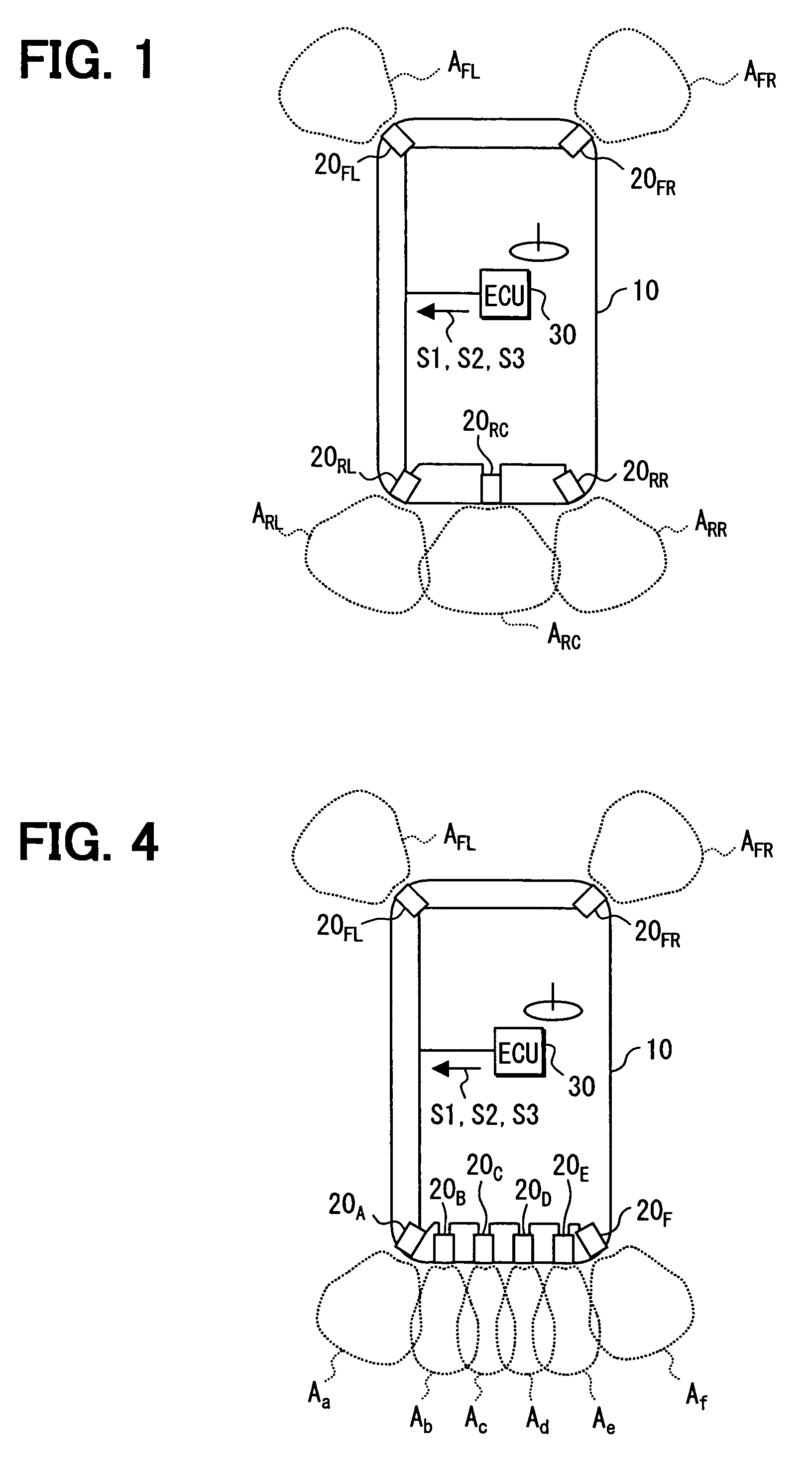
[0032]An obstacle detection device according to a first embodiment of the present invention will be described with reference to FIGS. 1-3B. In this case, the obstacle detection device is suitably used for a vehicle to detect an obstacle around the vehicle. The obstacle detection device has an ECU 30 and multiple detection units (e.g., ultrasound sensors 20FR, 20FL, 20RR, 20RC and 20RL) The ultrasound sensors 20FR, 20FL, 20RR, 20RC and 20RL (constructing ultrasound sensor system 20) are connected with the ECU 30 through a bus or the like.
[0033]The ultrasound sensors 20FR and 20FL are respectively attached to a right end and a left end of a front bumper of a vehicle chassis 10. The ultrasound sensors 20RR, 20RC and 20RL are respectively attached to a right end, a right-left-direction center portion, and a left end of a rear bumper of the vehicle chassis 10. Detection areas AFR, AFL, ARR, ARC and ARL around the vehicle are respectively allotted to the ultrasound sensors 20FR, 20FL, 20R...
second embodiment
[0065]A second embodiment of the present invention will be described with reference to FIGS. 4-6.
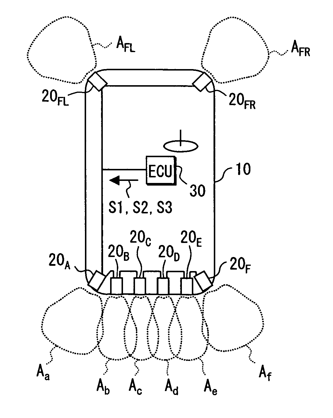
[0066]As shown in FIG. 4, six ultrasound sensors 20A-20F are mounted at the rear bumper of the vehicle chassis 10, and transmit and receive ultrasound signal (detection signal) respectively to detection areas Aa-Af, which are respectively allotted to the ultrasound sensors 20A-20F. In this case, the ultrasound sensors 20FL and 20FR are attached to the front bumper as described in the above-described first embodiment.
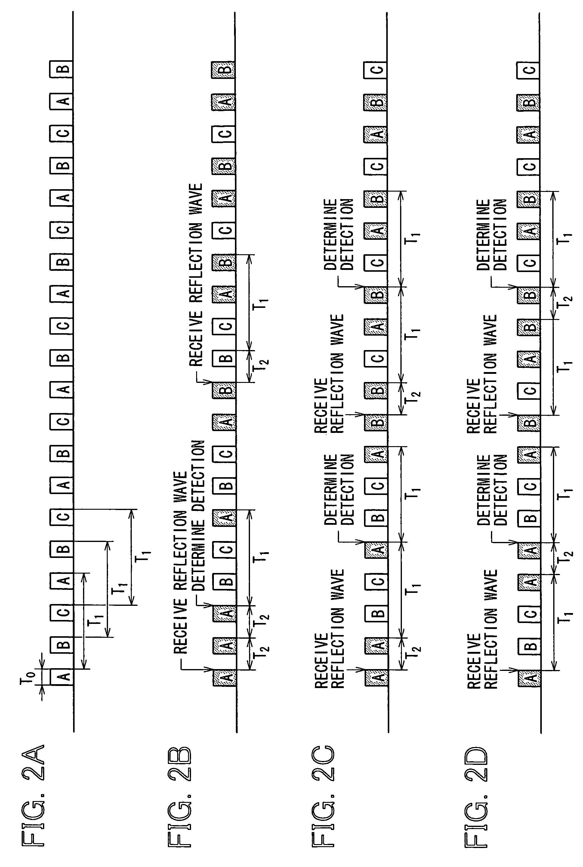
[0067]The ECU 30 outputs the operation timing signals S1-S3. The ultrasound sensors 20A-20F are divided into three groups A, B and C. Referring to FIG. 5A, the ultrasound sensor 20A and 20D are set to respond to the operation timing signal S1. That is, the group A includes transmission-reception operation objects of the ultrasound sensor 20A and 20D responding to the operation timing signal S1.
[0068]Referring to FIG. 5B, the ultrasound sensors 20C and 20F are set to respond t...
third embodiment
[0076]A third embodiment of the present invention will be described with reference to FIGS. 7-10.
[0077]In this case, as shown in FIG. 7, the vehicle is provided with the four ultrasound sensors 20FR, 20FL, 20RR and 20RL. The ultrasound sensors 20FR and 20FL are respectively attached to the right end and the left end of the front bumper. The ultrasound sensors 20RR and 20RL are respectively attached to the right end and the left end of the rear bumper. The detection areas AFR, AFL, ARR and ARL are respectively allotted to the ultrasound sensors 20FR, 20FL, 20RR and 20RL.
[0078]Each of the ultrasound sensors 20FR, 20FL, 20RR and 20RL performs the ultrasound transmission-reception operation, for respectively sending the ultrasound burst (send wave) to the detection area allotted thereto and receiving the ultrasound burst (reflection wave) reflected by an obstacle in the case where the obstacle exists in the detection area. Moreover, the transmission-reception operation includes the send...
PUM
 Abstract
Description
Claims
Application Information
 - R&D
- Intellectual Property
- Life Sciences
- Materials
- Tech Scout
- Unparalleled Data Quality
- Higher Quality Content
- 60% Fewer Hallucinations
Browse by: Latest US Patents, China's latest patents, Technical Efficacy Thesaurus, Application Domain, Technology Topic, Popular Technical Reports.
© 2025 PatSnap. All rights reserved.Legal|Privacy policy|Modern Slavery Act Transparency Statement|Sitemap|About US| Contact US: help@patsnap.com