Method of supplying oil from a floating production structure to an offloading buoy via a thermally insulated flexible transfer duct

a transfer duct and floating production structure technology, applied in the direction of passenger handling apparatus, special purpose vessels, borehole/well accessories, etc., can solve the problems of increasing the viscosity of hydrocarbons, reducing flow capacity, and steel pipes subject to metal fatigue, so as to reduce the heat loss through the duct, the effect of constant viscosity and reduced heat loss

Inactive Publication Date: 2010-02-23
SINGLE BUOY MOORINGS INC
View PDF11 Cites 1 Cited by
  • Summary
  • Abstract
  • Description
  • Claims
  • Application Information

AI Technical Summary

Benefits of technology

[0012]By providing a single, large diameter duct, instead of a bundle of ducts, the surface area of the duct, and hence the resultant heat loss through the surface of the duct is reduced. By providing a sufficient wall thickness, for instance by providing a wall thickness of elastomeric material between 3 cm and 7 cm, or by providing an insulation layer around the duct such as a layer of polystyrene material of a thickness of between 2 cm and 10 cm, the heat loss through the duct is reduced and crude oil can be pumped at reduced and substantially constant viscosity, such as between 40 cP at 40° C. and 8 cP at 50° C., at low pumping pressures.
[0013]Preferably the heat transfer coefficient of the mid depth transfer duct is between 0.1 and 0.5 W / mK. In particular at water temperatures of between 4° C. and 10° C., the low eat transfer coefficient results in a reduced heat loss over the length of the transfer duct, and in a substantially constant, low viscosity of the crude oil over the whole length of the transfer duct.

Problems solved by technology

Due to the weight of the steel pipes and their limited flexibility, these steel pipes are subject to metal fatigue.
When hydrocarbons, such as oils are transported through the known mid-water transfer pipes, heat loss through these pipes results in increased viscosity of the hydrocarbons and reduced flow capacity.

Method used


Image

  • Method of supplying oil from a floating production structure to an offloading buoy via a thermally insulated flexible transfer duct
  • Method of supplying oil from a floating production structure to an offloading buoy via a thermally insulated flexible transfer duct
  • Method of supplying oil from a floating production structure to an offloading buoy via a thermally insulated flexible transfer duct

Examples


Embodiment Construction

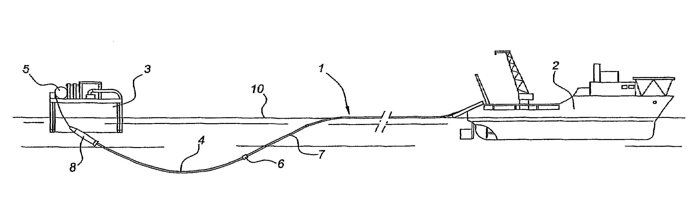
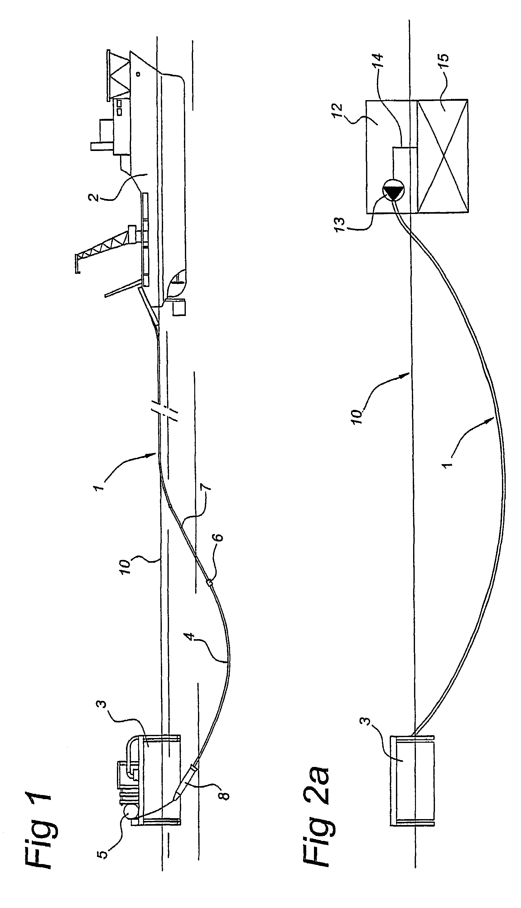
[0020]FIG. 1 shows a flexible mid depth transfer hose 1, which is deployed from a dynamically positioned supply vessel 2. The transfer hose 1 is connected to a CALM offloading buoy 3 via a pull-in wire 4, connected to a winch 5 on the buoy. By winding up the pull in wire 4 on the winch, a connector head 6 on flooded hose section 7 can be pulled in and locked in connector 8 at the bottom of the buoy 3. The flexible hose 1 has a length of between 1500 m and 3000 m and extends at a depth of between 50 m and 500 m below water level 10. The end of the hose 1 at the side of the supply vessel 2 is connected to a floating structure 12, such as an FPSO, a TLD (Tension Leg Deck), SPAR or Semi-submersible such as shown if FIGS. 2a-2d. On the floating structure 12, the hose 1 is connected to a pump unit 13, which is connected with an inlet duct 14 to a tank 15 or other oil supply source.

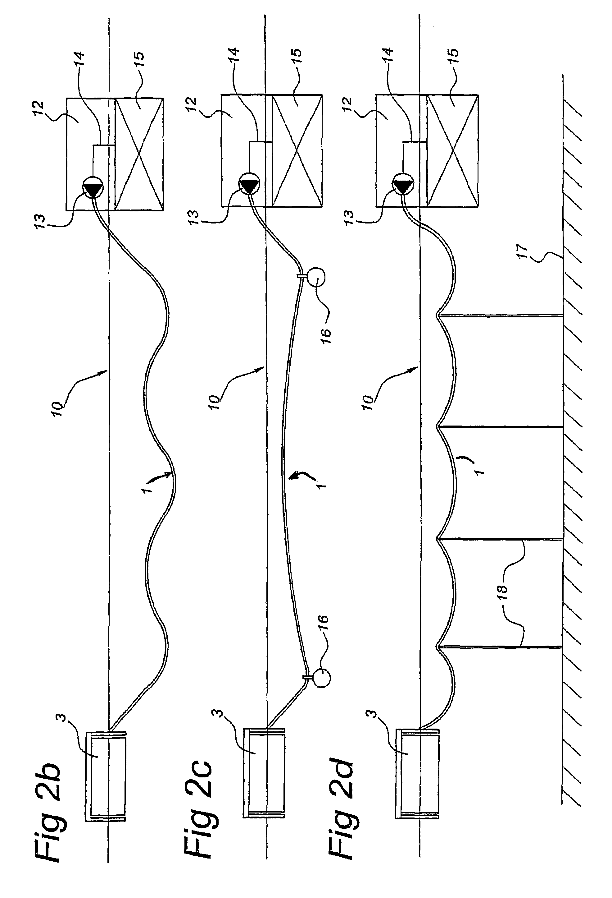
[0021]FIG. 2a shows a simple catenary configuration of the flexible hose 1, FIG. 2b a wave configuration, FIG...


PUM


Abstract

Method of supplying oil from a first floating structure to an offloading structure, includes providing a flexible duct extending between the two structures at a water depth of between 50 m and 500 m, the duct including a flexible elastomeric material and having an internal diameter of at least 600 mm and a length of between 1500 and 3000 m,
    • providing at least one pump at the first structure and pumping the oil through the duct at a pressure between 5 bar and at a flow rate between 1000 and 50,000 m3/hr,
    • providing a single flexible duct, and
    • providing a wall thickness of the duct such that at water temperatures between 2° C. and 20° C., the oil has at the first structure an inlet temperature Tin and at the second structure an outlet temperature T0 that Tin-T0 is smaller that or equal to 15° C., preferably smaller than 5° C.

Description

BACKGROUND OF THE INVENTION[0001]1. Field of the Invention[0002]The invention relates to a method of supplying oil from a first floating structure to an offloading structure, comprising the steps of:[0003]providing a flexible duct extending between the two structures at a water depth of between 50 m and 500 m, the duct comprising a flexible elastomeric material and having an internal diameter of at least 600 mm and a length of between 1,500 and 3,000 m, and providing at least one pump at the first structure and pumping the oil through the duct at a pressure between 5 bar and 30 bar and at a flow rate between 1,000 and 50,000 m3 / hr.[0004]2. Description of the Related Art[0005]Such flexible ducts are known from WO 02 / 44607, in which a marine hose is described which may have a length of 2 km or more, extending between an oil rig, FPSO, TLP, SPAR or Semi submersible, and an offloading buoy, such as a catenary anchor leg mooring (CALM) buoy, at depths between 80 and 30 meters. The known ...

Claims


Application Information

Patent Timeline
Patent Type & Authority Patents(United States)
IPC IPC(8): B63B22/02B67D9/00F16L1/12F16L59/14
CPCF16L1/12F16L59/143B63B27/34
Inventor WILLE, HEINROODUIJN, ERIK JAN
Owner SINGLE BUOY MOORINGS INC
Why Eureka
Try Eureka