
Method for fabrication MEMS-resonator

a technology of resonators and etching rates, applied in the field of resonators, can solve the problems of easy introduction of dimension errors into the vibration portion, uncontrollable errors, etc., and achieve the effect of uniform variation in the etching rate and excellent size control natur

Inactive Publication Date: 2010-02-23
LAPIS SEMICON CO LTD
View PDF10 Cites 46 Cited by
  • Summary
  • Abstract
  • Description
  • Claims
  • Application Information

AI Technical Summary

Benefits of technology

The approach results in MEMS resonators with improved size control and reduced variations in resonance frequency, achieving more accurate and consistent performance.

Problems solved by technology

However, in fabricating of the above-mentioned conventional type resonator, there was a problem that a dimension error is easy to be introduced into the vibration portion by a formation process of the vibration portion.
This micro loading effect causes an uncontrollable error to occur depending on pattern density near the vibration portion in a size of the vibration portion.

Method used


Image

  • Method for fabrication MEMS-resonator
  • Method for fabrication MEMS-resonator
  • Method for fabrication MEMS-resonator

Examples


modified embodiment 1

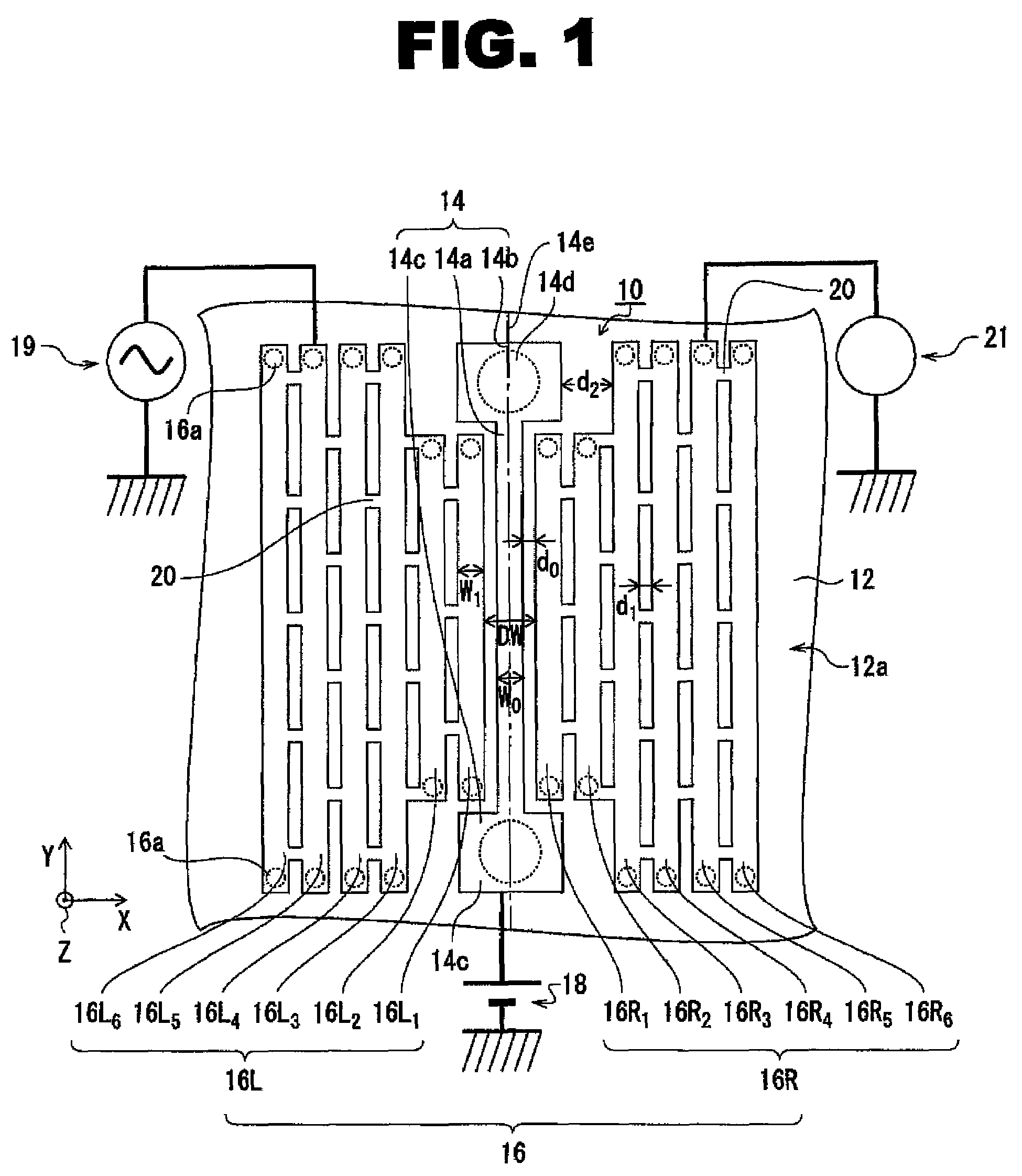
[0169]This embodiment explained the case where outputting part 21 for extracting an output is connected to the first electrode terminal group 16R, as shown in FIG. 1. However, the outputting part 21 does not necessarily need to provide in the first electrode terminal group 16R.

[0170]For example, as shown in FIG. 7, the outputting part 21 may be connected to the fixed part 14b of the opposite side of the fixed part 14c to which the direct current power supply 18 is connected. In this case, it is preferred to provide a coupling capacitor 46 for removing a dc component from output signal between the outputting part 21 and the fixed part 14b.

[0171]In addition, in this case, so to speak, the first electrode terminal group 16R functions as dummy cathode, and does not play a positive role about the input / output of a signal.

modified embodiment 2

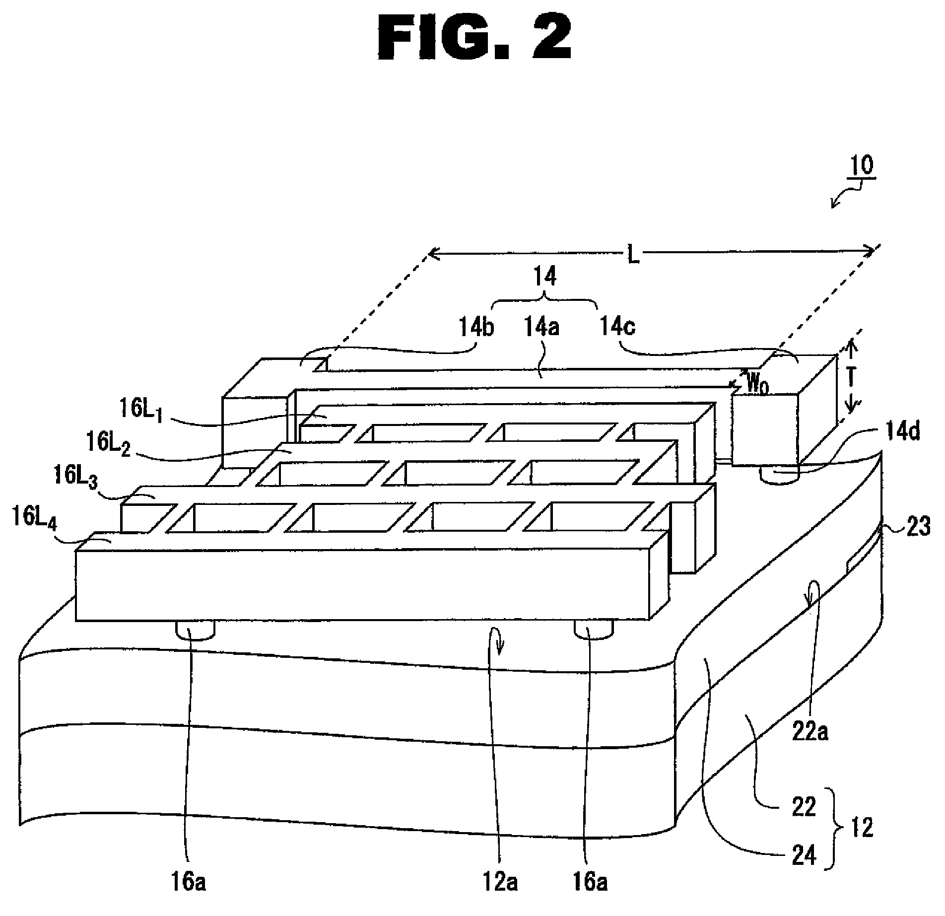
[0172]As shown in FIGS. 1 and 2, at this embodiment, the electrode terminal 16R1-16R6 and 16L1-16L6 are fixed to base substance 12 only by the plugs 16a, 16a . . . which are provided in both ends, and each inter-electrode is connected by the bridges 20, 20 . . . .

[0173]This is for the electrode terminals 16R1-16R6 and 16L1-16L6 (in particular the electrode terminals 16L1 and 16R1) to prevent vibrating synchronizing with the oscillator 14. Therefore, if vibration interlocked with the oscillator 14 of the electrode terminals 16R1-16R6 and 16L1-16L6 can be prevented, the fixing method of an electrode terminal is not limited to the aspect of FIGS. 1 and 2.

[0174]For example, as shown in FIG. 8, plenty of plugs 50, 50 . . . connected to the base substance 12 may be provided in the electrode terminal 48, without using the bridges 20, 20 . . . . Also by composing in this way, vibration which synchronized with the oscillator 14 of the electrode terminal 48 (481-484) can be prevented.

[0175]In...

modified embodiment 3

[0176]In this embodiment, the length of the electrode terminals 16R3-16R6 and 16L3-16L6 is explained the case where the length is equal to the overall length along in the direction of Y of the oscillator 14.

[0177]However, the length of the electrode terminals 16R3-16R6 and 16L3-16L6 is not limited to this length, if a micro loading effect can be made uniform or substantially uniform in the practically permissible range.

[0178]For example, as shown in FIG. 9, it is effective also considering the length of the electrode terminals 16R3-16R6 and 16L3-16L6 is equal to the length of the electrode terminals 16R1, 16R2, 16L1, and 16L2.

[0179]When it does in this way, the parasitic capacitance occurred between the fixed parts 14b and 14c and the electrode can be further reduced. Therefore, the level of signals (noise) except resonance frequency can be reduced compared with conventionally, and the effective signal of S / N can be extracted from the outputting part 21.

1>

[0180]This embodiment expla...


PUM


Abstract

The present invention is an etching mask used for fabricating of the MEMS resonator including an oscillator which both edges are fixed to a base substance and vibrates to a vibrating direction, and an electrode which is fixed to a base substance by vibration is impossible in parallel for the oscillator, and is placed every one or more at the both sides of the oscillator. The etching mask includes a mask pattern 36 for oscillators which covers an oscillator formation scheduled region 34 on a conductive film 30 formed all over a sacrificial film which covers a region of the principal surface except both edges of the oscillator, and a mask pattern 40 for electrodes which covers an electrode formation scheduled region 38 on a conductive film. The width about a vibrating direction of a mask pattern for oscillators and a mask pattern for electrodes is made the same, and a gap between a mask pattern for oscillators and a mask pattern for electrodes and a gap between adjoining mask patterns for electrodes are made the same.

Description

CROSS REFERENCE TO RELATED APPLICATION[0001]This application claims the priority of Application No. 2007-077538, filed Mar. 23, 2007 in Japan, the subject matter of which is incorporated herein by reference.TECHNICAL FIELD OF THE INVENTION[0002]This invention relates to a resonator, and in particular, relates to a method for fabricating a MEMS (micro Electro Mechanical Systems) resonator, and an MEMS resonator itself.BACKGROUND OF THE INVENTION[0003]A MEMS resonator provided with a beam-shaped vibration portion where both edges are fixed, and an electrode provided near this vibration portion is known (for example, refer to patent document 1 and non-patent document 1). The resonator described in patent documents 1 and non-patent document 1 (it is also hereafter referred to “conventional type resonator”) vibrates the vibration portion using the change of electrostatic capacity of the vibration portion which occurs by impressing alternating voltage to the electrode.[0004]It is known th...

Claims


Application Information

Patent Timeline
Patent Type & Authority Patents(United States)
IPC IPC(8): H01L21/00
CPCB81C1/00579B81B2201/0271
Inventor IGARASHI, YASUSHI
Owner LAPIS SEMICON CO LTD
Learn More