Clock reproducing apparatus
a clock and apparatus technology, applied in the field of clock reproducing apparatus, can solve the problems of inability to use methods, inability to perform well oscillation, and inability to achieve stable oscillation operation, etc., and achieve the effect of stable oscillating operation
- Summary
- Abstract
- Description
- Claims
- Application Information
AI Technical Summary
Benefits of technology
Problems solved by technology
Method used
Image
Examples
first embodiment
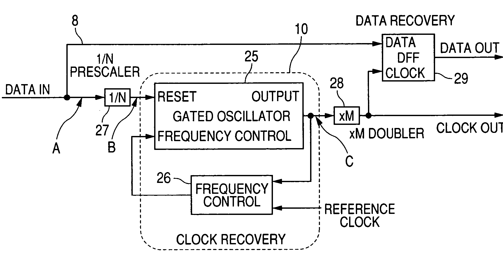
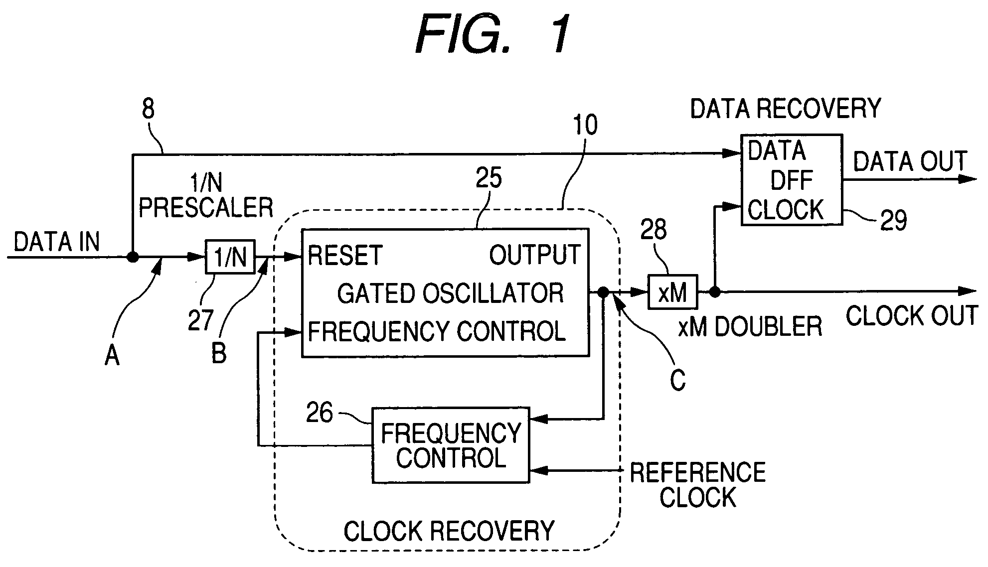
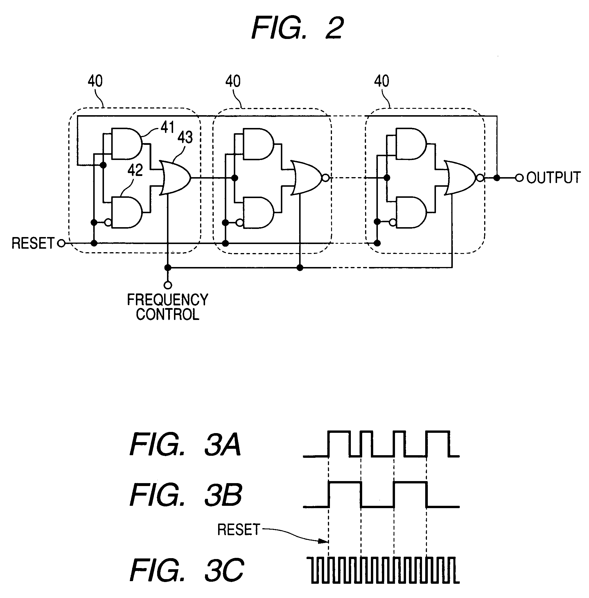
[0071]FIG. 1 is a block diagram for showing a clock reproducing apparatus of the present invention. In this drawing, reference numeral 10 indicates a clock reproducing circuit. The clock reproducing circuit 10 includes a gated oscillator 25, and a frequency control circuit 26 for comparing an output of the gated oscillator 25 with a reference clock, and for supplying a phase control signal for setting a delay time to the gated oscillator 25 based on a comparison result. Reference numeral 27 shows a 1 / N frequency divider or a prescaler for dividing a frequency of input data by 1 / N, and reference numeral 28 indicates an M frequency multiplier or M-doubler for multiplying an output of the clock reproducing circuit 10 by M, and an output of the M frequency multiplier 28 is input to a clock input terminal of a D type flip-flop (will be abbreviated as “DFF” hereinafter) 29. On the other hand, the input data is directly input via a signal line 8 (delay line) to a data input terminal of the...
second embodiment
[0085]FIG. 11 is a block diagram for showing a clock reproducing apparatus according to the present invention. In this drawing, reference numeral 120 shows a pulse forming circuit which receives input data (DATA In) so as to form a pulse from the received input data. Reference numeral 130 represents a clock reproducing circuit including a gated oscillator 131 and a frequency control circuit 132 for comparing an output of the gated oscillator 131 with a reference clock, and for supplying a phase control signal for setting a delay time to the gated oscillator 131 based on a comparison result.
[0086]The pulse forming circuit 120 is a circuit for generating a reset pulse in synchronism with an input signal (data). The clock reproducing circuit 130 is a circuit for reproducing a clock in synchronism with the reset pulse. In the pulse forming circuit 120, reference numeral 125 shows a frequency divider which divides the input signal by 1 / N, and reference numeral 126 represents a capacitor ...
third embodiment
[0097]FIG. 14 is a block diagram for showing a first structural example of a clock reproducing apparatus according to the present invention. It should be noted that the same reference numerals shown in FIG. 11 are employed as those for the same circuit elements, and explanation thereof are not repeatedly made. In the drawings, reference numeral 120A shows a pulse forming circuit. This pulse forming circuit 120A forms a reset pulse not by using a differentiating circuit, but by employing an AND circuit. Arrangements of a clock reproducing circuit 130, a frequency multiplier 141, and a DFF 142 are identical to those of FIG. 11. It should also be noted that as a gated oscillator, such a gated oscillator shown in FIG. 22 is employed.
[0098]A description is made of operations of the pulse forming circuit 120A in the circuit arranged in the above-explained manner. In this circuit, reference numeral 125 shows a 1 / N frequency divider. In this case, a ½ frequency dividing operation is represe...
PUM
 Abstract
Description
Claims
Application Information
 - R&D
- Intellectual Property
- Life Sciences
- Materials
- Tech Scout
- Unparalleled Data Quality
- Higher Quality Content
- 60% Fewer Hallucinations
Browse by: Latest US Patents, China's latest patents, Technical Efficacy Thesaurus, Application Domain, Technology Topic, Popular Technical Reports.
© 2025 PatSnap. All rights reserved.Legal|Privacy policy|Modern Slavery Act Transparency Statement|Sitemap|About US| Contact US: help@patsnap.com


