Control system, computer program product, device and method

a control system and computer program technology, applied in the field of control systems, can solve problems such as reducing the effectiveness of the control system, affecting the productivity of the system, and affecting the quality of the product, so as to achieve the effect of improving the productivity

Inactive Publication Date: 2010-03-02
ABB (SCHWEIZ) AG
View PDF13 Cites 14 Cited by
  • Summary
  • Abstract
  • Description
  • Claims
  • Application Information

AI Technical Summary

Benefits of technology

[0016]It is an object of this invention to provide on-line regulation of process parameters during a metal casting process to control and optimize casting conditions and consequently provide a cast product with a minimum of defects at the same or improved productivity.
[0019]Once vm has been inferred at least one process parameter is varied in order to maintain vm within a predetermined range or at a predetermined value in the range 0.1-0.5 ms−1, preferably in the range 0.2-0.4 ms−1. The control system actively regulates at least one process parameter to maintain the meniscus characteristic or vm within an optimum range and in this way provides conditions that minimize the emergence of blisters (formed by entrapped gas bubbles) and inclusions in the cast products.
[0026]Alternatively, at least one current pulse is provided by the electromagnetic means during their de-activation period in order to remove the remanence remaining after their de-activation, which further reduces the amount of error in the measurements.

Problems solved by technology

These impurities can either float to the top of the mould in the secondary flow where they become entrained harmlessly onto the slag layer at the meniscus, often after circulating within the mould, or they can be carried down into the lower parts of the mould in the primary flow and become trapped in the solidifying front leading to defects in the cast metal products.
If the metal flow velocity at the surface of the meniscus is too great it may shear off some of the slag layer and thereby form another source of harmful inclusions if they become entrapped in the cast products.
However if the surface flow is too slow the mould powder at the meniscus may cool to a too low temperature and solidify thus decreasing its effectiveness.
These velocity variations give rise to pressure and height variations at the meniscus which can result in slag being drawn into the lower part of the mould, an uneven slag thickness and a risk of crack formation.
However vm is difficult to measure directly.
A disadvantage with this method is that the standing wave has to be monitored over a period of time in order to detect a change before information indicating that a change has occurred can be fed to the control unit.
Oscillation of the mould during the monitoring period can affect the height, shape and location of the standing wave and thus adversely affect the accuracy of the monitoring.
A problem with using sensors that are based on electromagnetic induction is that they can experience interference from electromagnetic means such as the EMBR or stirring apparatus that are usually used in casting devices, which affects the accuracy of such sensors.

Method used


Image

  • Control system, computer program product, device and method
  • Control system, computer program product, device and method
  • Control system, computer program product, device and method

Examples


Embodiment Construction

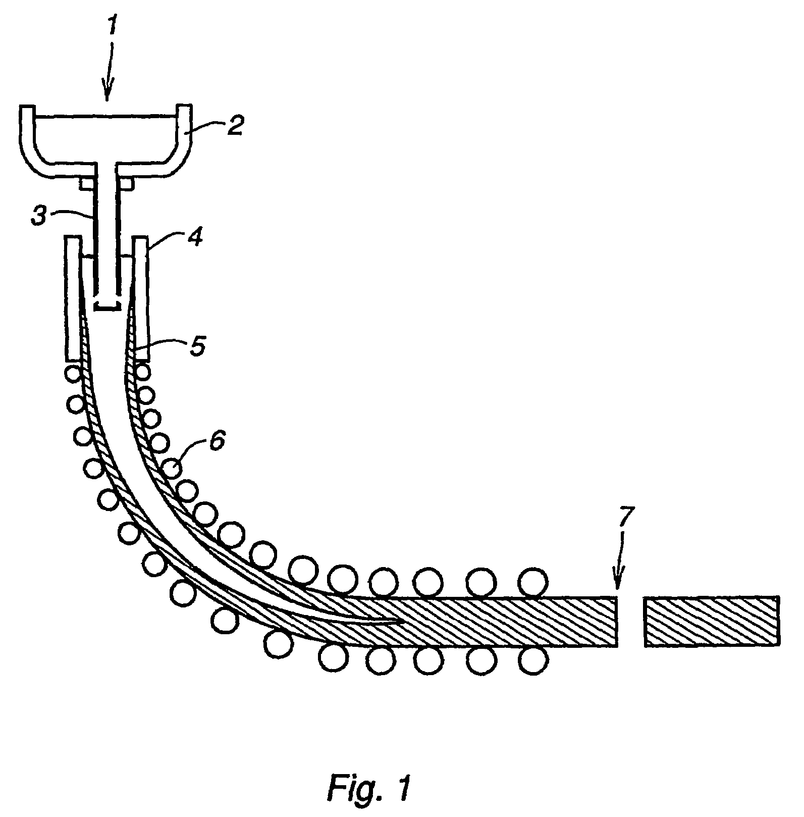
[0042]In the continuous casting device shown in FIG. 1 molten metal 1 is poured from a ladle (not shown) into a tundish 2. It then passes through a submerged entry nozzle 3 into a water-cooled mould 4 where the outer shell of the metal becomes solidified, producing a metal strand with a solid outer shell 5 and a liquid core. Once the shell has a sufficient thickness the partially solidified strand is drawn down into a series of rolls 6 where the strand becomes rolled into shape and fully solidified. Once the strand is fully solidified it is straightened and cut to the required length at the cut off point 7.

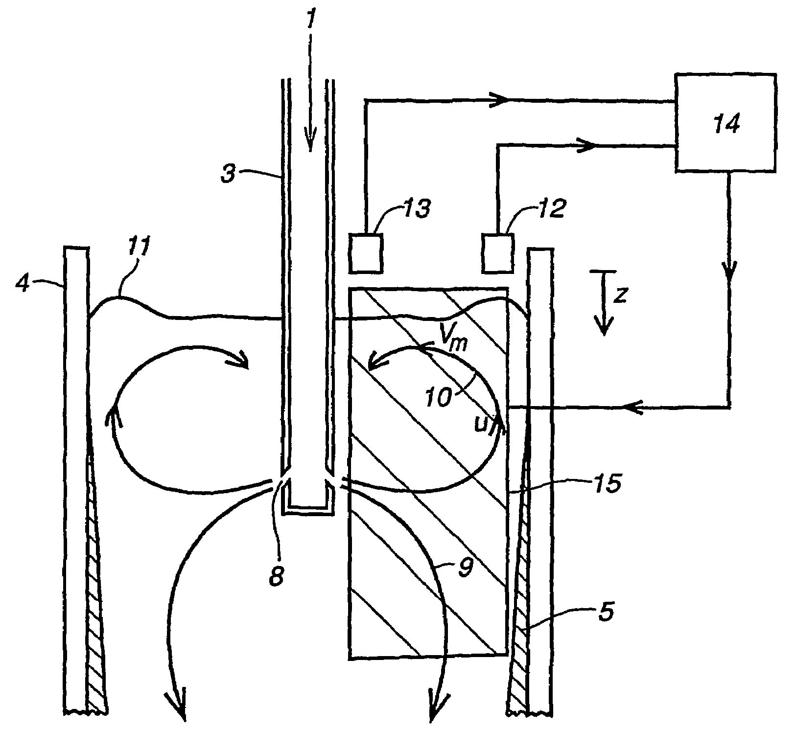
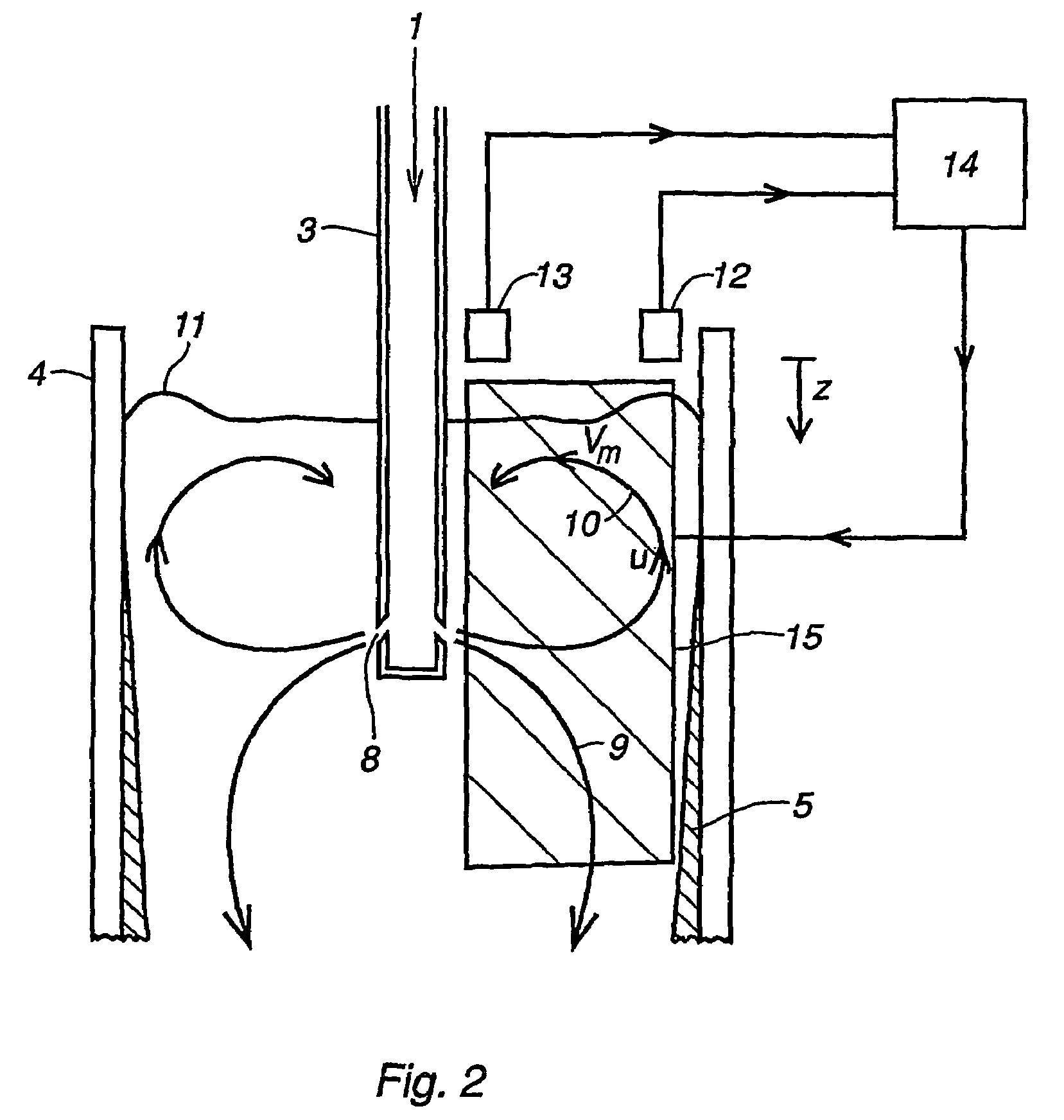
[0043]FIG. 2 shows the flow pattern of molten metal 1 entering a mould 4 via side ports 8 in a submerged entry nozzle 3. Inside the mould the flow circulates within the sides of the walls of solidifying metal 5. A primary flow 9 flows downwards in the casting direction. A secondary flow 10 flows upwards along the sides of the mould with a velocity u towards the meniscus 11. The ki...


PUM

PropertyMeasurementUnit
heightaaaaaaaaaa
velocityaaaaaaaaaa
flow velocityaaaaaaaaaa

Abstract

A control system for regulating the flow of liquid metal in a device for casting a metal. A detector measures a process variable. A control unit evaluates data from the detector. At least one process parameter is automatically varied in order to optimize casting conditions. The detector measures a characteristic of the meniscus at at least two points on the meniscus instantaneously throughout the casting process.

Description

[0001]The present invention claims priority from U.S. provisional patent application 60 / 429,884, filed 29 Nov. 2002 and Swedish patent application 0301049-3 filed 7 Apr. 2003 and is the national phase under 35 U.S.C. § 371 of PCT / SE2003 / 001857.TECHNICAL FIELD[0002]The present invention relates to a control system for regulating the flow of liquid metal in a device for casting a metal. The control system comprises detection means to measure a process variable, a control unit to evaluate the data from the detection means and means to automatically vary at least one process parameter such as the casting speed, noble gas flow rate, magnetic field strength of electromagnetic means, such as an electromagnetic brake or stirring apparatus, slab width, or immersion depth of a submerged entry nozzle in order to optimize the casting conditions. The present invention also concerns a computer program product, a device and method for casting a metal.BACKGROUND OF THE INVENTION[0003]In the continu...

Claims


Application Information

Patent Timeline
Patent Type & Authority Patents(United States)
IPC IPC(8): B22D11/16B22D27/02B22D
CPCB22D11/16B22D11/115B22D11/18
Inventor KOLLBERG, STENERIKSSON, JAN-ERIKLINDBERG, CARL-FREDRIKMOLANDER, MATSLOFGREN, PETERTALLBACK, GOTEBEL FDHILA, REBEISAMUELSSON, BERTILISRAELSSON TAMPE, STEFANWALLIN, CHRISTINA
Owner ABB (SCHWEIZ) AG
Why Eureka
Try Eureka