Clamp for mount system

a technology of mounting system and mounting plate, which is applied in the direction of furniture parts, instruments, signs, etc., can solve the problems of data collector falling from the support, and the accuracy of surveying, and achieve the effect of preventing deformation of the geomatics suppor

Active Publication Date: 2010-03-02
SECO PRECISION (USA) LLC +1
View PDF96 Cites 51 Cited by
  • Summary
  • Abstract
  • Description
  • Claims
  • Application Information

AI Technical Summary

Benefits of technology

[0009]Generally, a torque limiting rotary driver mechanism comprises a head having flanged ends, and a threaded shaft fixed to the head for conjoint rotation therewith. A resilient grip is adapted to be gripped and turned by a hand. The grip operatively bears against the head for rotation of the shaft up to a threshold torque. The grip is resiliently deformable such that upon reaching the threshold torque the grip is deformed thereby allowing the grip to rotate relative to the head and shaft.
[0010]In another aspect of the present invention, a clamp for attaching items to a geomatics support comprises an anvil sized and shaped for attachment to the geomatics support, and a jaw having a jaw member sized and shaped for attachment to a surface of the geomatics support. The jaw member is moveable relative to the anvil between a secured position of the jaw wherein the clamp is secured to the geomatics support and an unsecured position of the jaw wherein the clamp can be moved relative to the geomatics support. A driver moves the jaw member between the secured position and unsecured position. The driver includes a torque limiter to inhibit overtightening of the jaw against the geomatics support and thereby prevent deformation of the geomatics support.

Problems solved by technology

One difficulty with mounting the holder directly, to the surveying pole or tripod is that surveying implements, once positioned to collect survey data, often cannot be disturbed without compromising the accuracy of the survey.
Since there is no positive connection between the support and the data collector, the device must be removed from the support before moving the pole or tripod otherwise the data collector will fall from the support and be damaged.
Requiring the data collector to be carried separately is highly inconvenient for surveyors who may work in remote locations and manually transport their equipment.
While this arrangement prevents the data collector from falling from the support, it is difficult to manually enter survey data or descriptions of surveyed locations since the data collector cannot be simply picked up off the support.
Moreover, the act of connecting the data collector to the support typically requires discontinuous motion, such as turning a screw knob, which may result in undesired vibration or movement of the tripod or pole thereby compromising accuracy of the survey.
In addition, the angle at which the support holds the data collector greatly affects the ability of the data collector to be used or viewed.
Thus, this is a somewhat time consuming process that requires two hands and could easily result in the undesired movement of the pole or tripod.
As a result, left-handed surveyors typically have to reach across their bodies to manipulate the data collector.
This is particularly inconvenient when they must simultaneously hold the pole.
Another adverse effect of the small area of contact is that the clamp is still unstable.
Moreover, the screw and screw knob arrangement is prone to overtightening.
Thus, this arrangement can cause irreparable damage to poles or tripods by repeated tightening (or overtightening) of the clamp to the same position on the pole.

Method used


Image

  • Clamp for mount system
  • Clamp for mount system
  • Clamp for mount system

Examples


Embodiment Construction

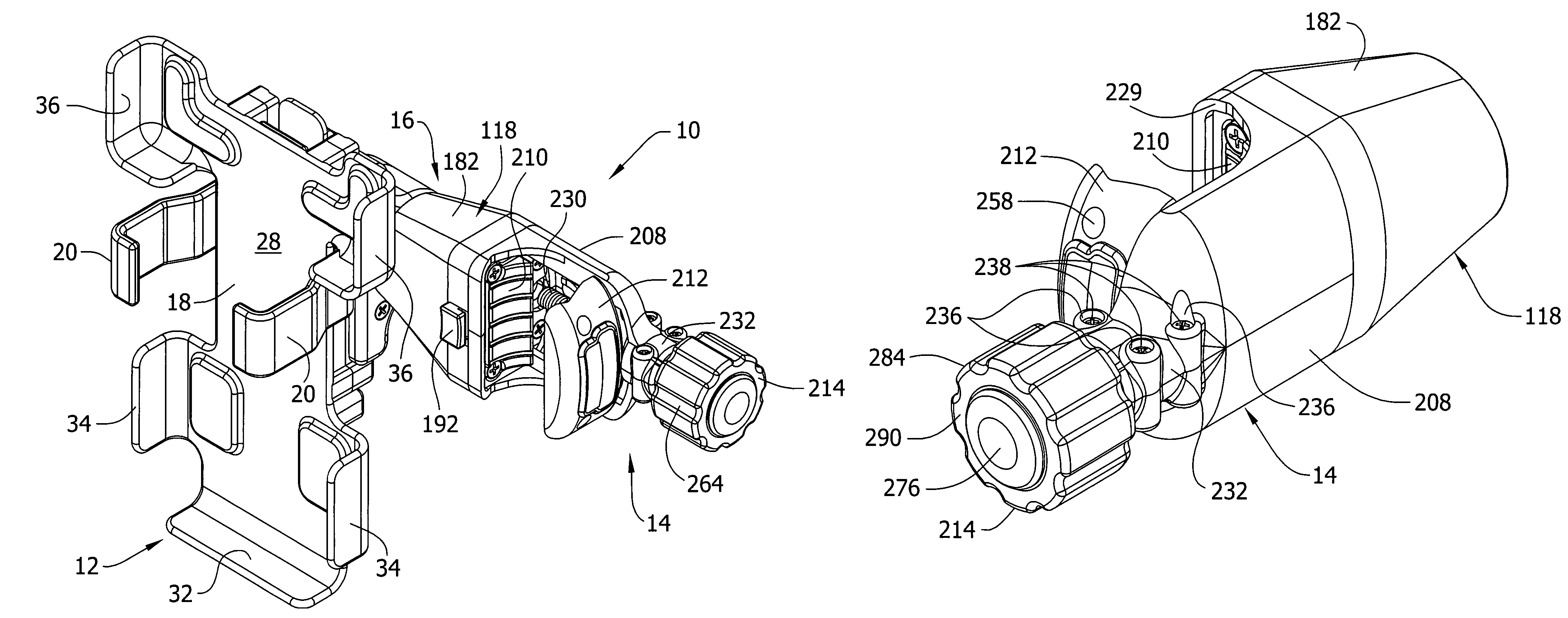
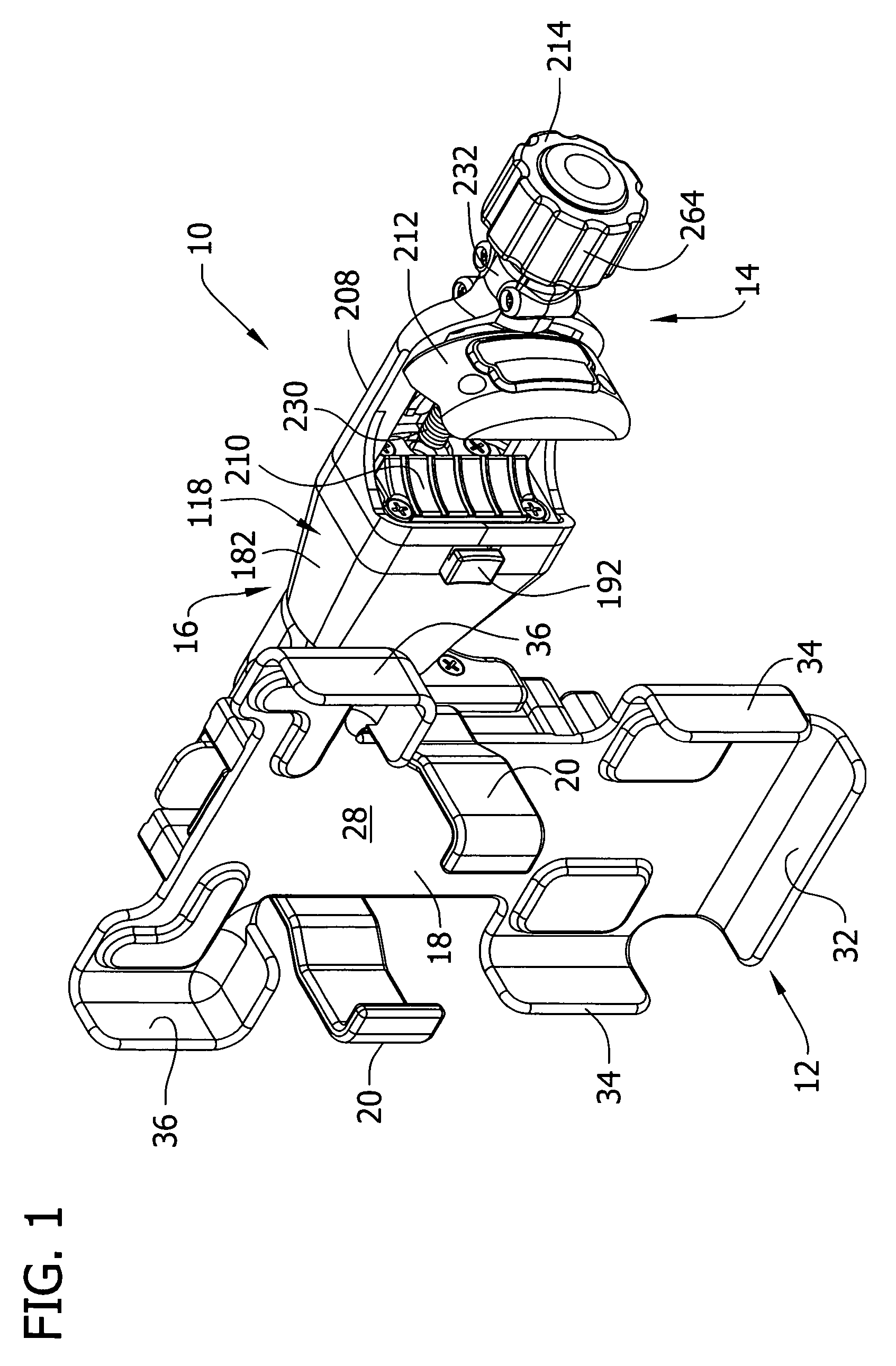
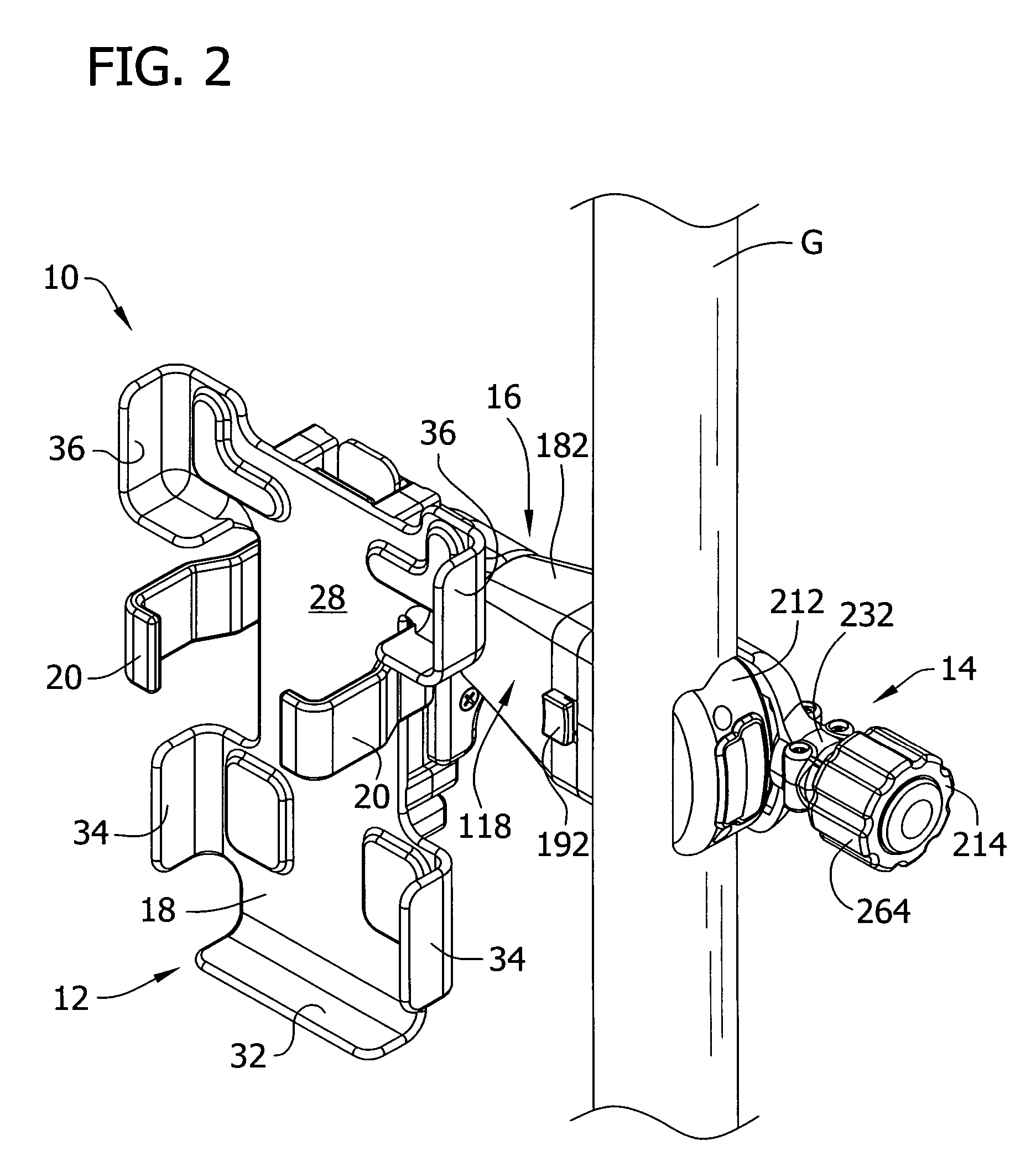
[0058]Referring now to the drawings, and in particular to FIGS. 1-5, a handheld electrical device mount system of the present invention, generally indicated at 10, is shown. The mount system 10 includes a cradle 12 (broadly, “holder”) for supporting an electrical device such as data collector D, a clamp 14 for securing the cradle to an object, and a coupler 16 connecting the cradle to the clamp (the numbers designating their subjects generally). The mount system 10 is shown attached to a geomatics pole G (FIG. 2) and a tripod T (FIG. 3). Details of a suitable geomatics pole and a suitable tripod (broadly, “geomatics supports”) can be found in co-assigned U.S. Pat. Nos. 6,772,526 and 6,685,566, respectively, which are incorporated herein by reference in their entireties. As used herein “geomatics” is intended to encompass surveying and geographic positioning.

[0059]The mount system 10 can be attached to objects other than geomatics poles, tripods, or other geomatics equipment without ...


PUM


Abstract

A clamp comprises an anvil and a jaw member moveable relative to the anvil between a secured positioned and an unsecured positioned. A driver, which moves the jaw member between the secured and unsecured positions, includes a torque limiter to inhibit overtightening the jaw member against an object. The jaw member has a rigid engagement portion and an elastomeric pad on its engagement surface. In the unsecured position, the elastomeric pad projects above the rigid material such that when the jaw member is brought into contact with the object, the elastomeric pad contacts the object and the object is substantially free of contact with the rigid engagement portion. In the secured position, the elastomeric pad is compressed such that both the elastomeric pad and rigid engagement portion contact the object.

Description

BACKGROUND OF THE INVENTION[0001]This invention relates generally to devices that support and hold equipment and more particularly to a clamp for a mount system for holding handheld electrical devices.[0002]Handheld electrical devices, such as handheld computers (e.g., data collectors, PDAs, Blackberrys™) and cellular phones, are widely used and have many applications. For example, many land surveyors use handheld electrical data collectors to record and store field measurements, perform calculations, verify data accuracy, and even generate plots. Data collectors equipped for surveying can be connected directly to surveying equipment (e.g., a total station) for recording data and then to a PC or notebook computer for transferring the data from the data collector. Thus, data collectors allow surveyors to quickly, easily, and accurately collect surveying data and transfer it to a PC or notebook computer.[0003]During a survey of land, the data collector is commonly supported by a holde...

Claims


Application Information

Patent Timeline
Patent Type & Authority Patents(United States)
IPC IPC(8): F16B1/00A47B96/00F16M11/14
CPCF16M13/02G01C15/00F16M11/041F16M11/10F16M13/00F16M13/022F16M2200/027
Inventor CRAIN, STEPHEN B.MOORE, CHRISTOPHER T.MIZE, RALPH C.WILLIAMSON, JERRY L.
Owner SECO PRECISION (USA) LLC
Why Eureka
Try Eureka