
RF body coil with acoustic isolation of conductors

a technology of acoustic isolation and conductor, which is applied in the field of rf coil, can solve the problems of uncontrollable difficult control of inability to eliminate all acoustic noise from the rf coil, so as to reduce the acoustic output

Active Publication Date: 2010-03-02
GENERAL ELECTRIC CO
View PDF20 Cites 12 Cited by
  • Summary
  • Abstract
  • Description
  • Claims
  • Application Information

AI Technical Summary

Benefits of technology

Effectively reduces acoustic noise by decoupling vibrations and lowering the natural frequency of the RF coil, thereby minimizing noise transmission to the support form.

Problems solved by technology

One of the difficulties of such MR scanners, however, is that the noise level can become uncomfortably loud, both for the patient, or subject, and for the operators.
The noise from the RF coil is due to Lorentz forces set up in the RF conductors and, while other acoustic noise sources in the MR scanner can be addressed by standard vibration isolation techniques, the acoustic noise from the RF coil is more difficult to control due to its close proximity to the patient, or subject, bore.
These attempts, however, have not been able to eliminate all of the acoustic noise from the RF coil.

Method used


Image

  • RF body coil with acoustic isolation of conductors
  • RF body coil with acoustic isolation of conductors
  • RF body coil with acoustic isolation of conductors

Examples


Embodiment Construction

[0018]A system is shown to isolate vibration, reduce the vibration natural frequency, and reduce acoustic noise in the RF coil of an MR imaging apparatus.

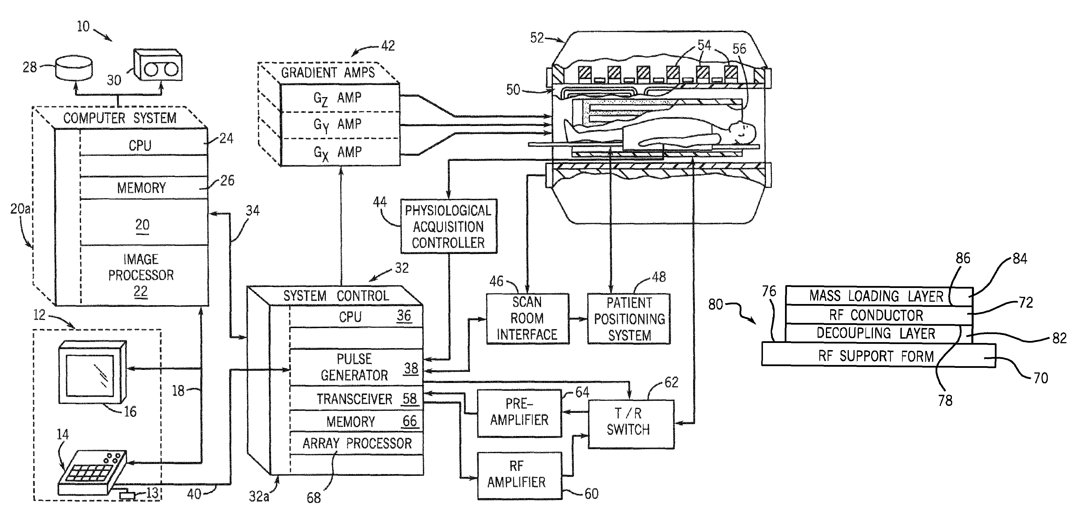
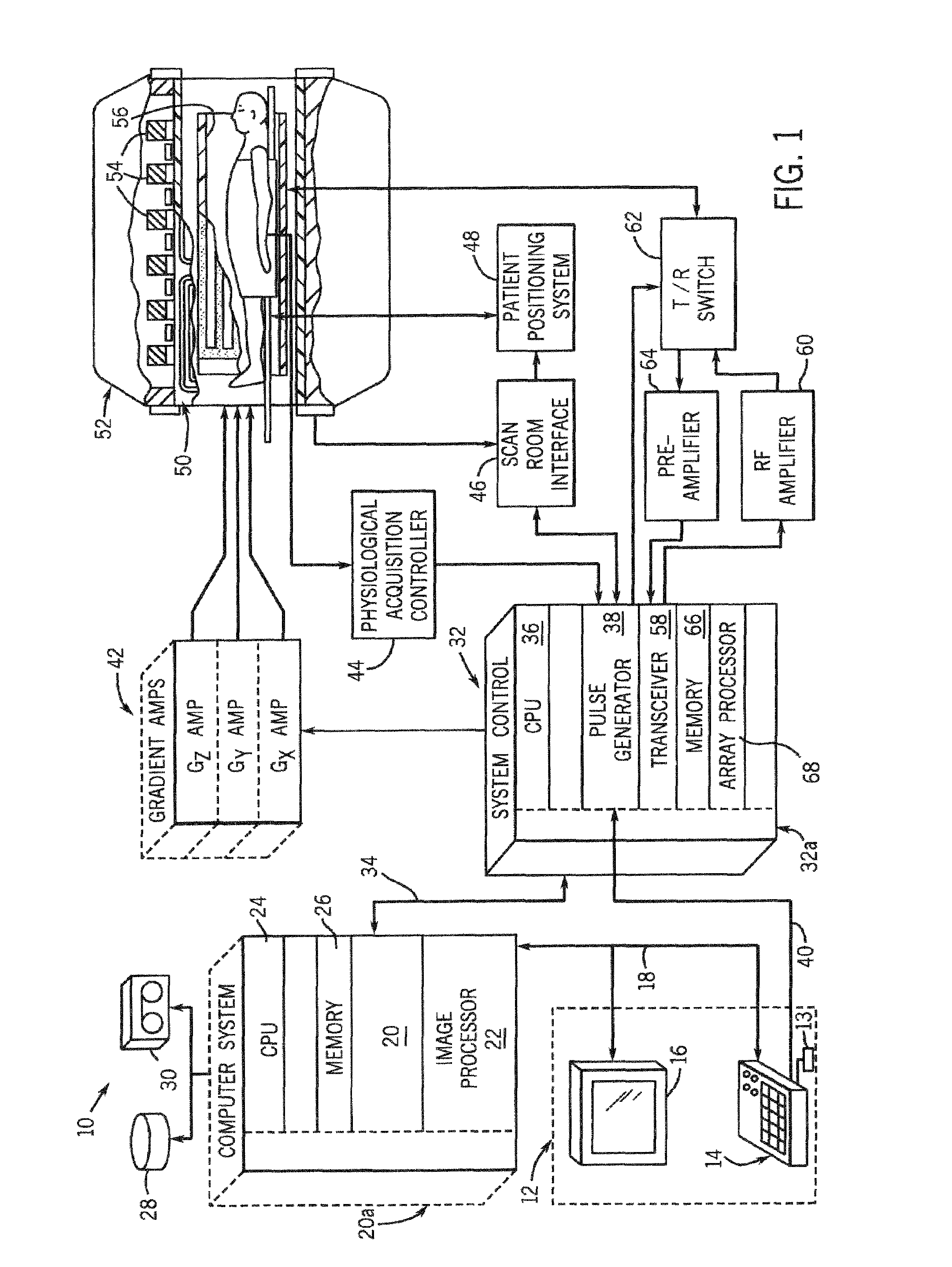
[0019]Referring to FIG. 1, the major components of a preferred magnetic resonance imaging (MRI) system 10 incorporating the present invention are shown. The operation of the system is controlled from an operator console 12 which includes a keyboard or other input device 13, a control panel 14, and a display screen 16. The console 12 communicates through a link 18 with a separate computer system 20 that enables an operator to control the production and display of images on the display screen 16. The computer system 20 includes a number of modules which communicate with each other through a backplane 20a. These include an image processor module 22, a CPU module 24 and a memory module 26, known in the art as a frame buffer for storing image data arrays. The computer system 20 is linked to disk storage 28 and removable storage 30 for s...


PUM


Abstract

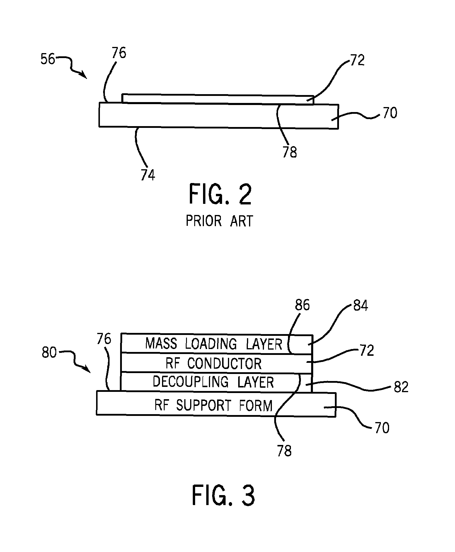
A system for isolating vibration and reducing acoustic noise in the RF coil of an MR imaging apparatus is presented. The system positions an RF conductor in its operative position proximate to an RF support form. The RF conductor is sandwiched between a vibration decoupling layer and a mass loading layer. The vibration decoupling layer is affixed to the RF support form so that the vibration decoupling layer is positioned between the RF conduit and the RF support form while the mass loading layer is located exterior of the RF conductor. By this arrangement, the acoustic energy is decoupled from the RF support form by the vibration decoupling layer while the vibration is reduced by the mass loading layer located exterior of the RF conductor.

Description

BACKGROUND OF THE INVENTION[0001]The present invention relates generally to an RF coil used in an MR imaging system, and, more particularly, to an RF coil having enhanced acoustic deadening properties.[0002]With MR scanners, the apparatus basically includes an RF coil that surrounds the subject and which directs the RF energy toward the subject or which receives RF energy from the subject, in carrying out the scanning process.[0003]One of the difficulties of such MR scanners, however, is that the noise level can become uncomfortably loud, both for the patient, or subject, and for the operators. The source of such acoustic noise can be many and varied, however, the RF coil has been shown to be a major contributor.[0004]The noise from the RF coil is due to Lorentz forces set up in the RF conductors and, while other acoustic noise sources in the MR scanner can be addressed by standard vibration isolation techniques, the acoustic noise from the RF coil is more difficult to control due t...

Claims


Application Information

Patent Timeline
Patent Type & Authority Patents(United States)
IPC IPC(8): G01V3/00
CPCG01R33/34046G01R33/341G01R33/288
Inventor GOLDHABER, DAVID M.HALLMAN, DARREN LEELINZ, ANTON MAX
Owner GENERAL ELECTRIC CO
Learn More